ALU Implementation - the road traveled thus far

classic Classic list List threaded Threaded
24 messages Options
12
Reply | Threaded
Open this post in threaded view
|

ALU Implementation - the road traveled thus far

ouverson
This post was updated on .
Hello,

I'm not really looking for an answer to a question; but rather a thumbs-up that I'm on the right track regarding my thoughts on ALU implementation.

My initial thoughts on ALU implementation were:
* Am I to view the table with inputs and outputs as a Truth Table? If so, how am I to think about implementation within that context?
* It looks as if there are many "if statements" staring me in the face: if this, and if this, then this implementation to achieve outputs. Not sure how I would wire-up chips to achieve this logic.
* I'm sure I'm supposed to be using previously implemented chips/gates; not only the ones from chapter/week 2, but from chapter/week 1. Let me take a look at all the previously implemented chips/gates and see which ones would stand out; many did.
* This Two's Complement thing is important. How exactly I'm not sure; it will probably become apparent/obvious.
* As with other chip/gate implementation there's probably a "key" (some tool such as canonical representation) that turns the lock; finding the key is half the fun (and frustration) LOL.

The road traveled thus far:


Starting with a primitive Nand gate I have built increasing complex chips/gates.

The tools I have used:
* Truth Table
* Canonical Representation (a type of Boolean Expression)
* Some basic Algebraic rules

I did a study of chip/gate progression with the thought that I would be able to see a pattern and also see which chips/gates would probably be used in my ALU implementation; maybe all of them?!

How to take all this and begin the ALU implementation? Not sure what the first step should be.
Reply | Threaded
Open this post in threaded view
|

Re: ALU Implementation - the road traveled thus far

WBahn
Administrator
If you would, please edit your post to remove the Implementation portion of your part descriptions. In some cases it provides too much of a hint to people trying to figure out how to implement that part. Give them the opportunity to mull it over and struggle with it a bit.

While the table you are referring to (I'm assuming it's Figure 2.6) is a truth table, the output is given in functional form, so it's not a simple matter of writing an expression in canonical form.

Break the problem down into very small pieces -- you will find the ALU is almost trivial to implement if you do.

Take each of the control signals one by one and ask yourself what parts could you use to make just that part happen. Treat each as a black box. If you do that, you don't even need to have the last column of the truth table -- it just documents what you get if you do what each of the inputs tells you to do.

For instance, if the zx input is 0, you want a black box that takes the input x and simply passes it to the output, while if zx is 1 you want to present a 0 at the output. Make a part (or a couple lines of HDL code) to do that and you are done with that control signal.

One tricky part to watch out for is the description for nx is not actually referring to the original x input to the ALU, but rather to the x input as modified by the zx input (i.e., the output of the box described in the previous paragraph).

A better way of presenting this would have been to treat zx and nx as a pair of signals with the description:

nx zx out
 0   0   x
 0   1   0
 1   0  !x
 1   1  !0

Reply | Threaded
Open this post in threaded view
|

Re: ALU Implementation - the road traveled thus far

ouverson
Thank you for the helpful hints; this was my "gut feeling".

I still have some questions but want to take your hints and start to play around.

Thanks again!

P.S. I removed my previously implemented gates.
Reply | Threaded
Open this post in threaded view
|

Re: ALU Implementation - the road traveled thus far

ouverson
In reply to this post by WBahn
I'm not how to share something without giving away the answer to other students. I sent you an email by clicking on your handle "WBahn" and then clicking on "Send Email to WBahn".
Reply | Threaded
Open this post in threaded view
|

Re: ALU Implementation - the road traveled thus far

WBahn
Administrator
ouverson wrote
I'm not how to share something without giving away the answer to other students. I sent you an email by clicking on your handle "WBahn" and then clicking on "Send Email to WBahn".
I don't know if I got the e-mail you sent or not. I received a notification of a reply to this thread and that's all. I replied to it. If you don't get it, make a note here and we'll figure something else out.
Reply | Threaded
Open this post in threaded view
|

Re: ALU Implementation - the road traveled thus far

ouverson
This post was updated on .
I did send the email. I had system copy me in so I know it was sent. I wanted to share the HDL I’ve completed thus far. I suppose this isn’t the place to do that. Any suggestions?

But to get the ball rolling: I was wanting to use a Mux4Way16 and wire it up using sel[0]=zx and sel[1]=nx but the interface doesn't seem to allow that, or maybe I'm just not understanding the HDL syntax? Or maybe it would be better to wire together more Mux16s?
Reply | Threaded
Open this post in threaded view
|

Re: ALU Implementation - the road traveled thus far

ivant
In reply to this post by ouverson
It's alright to share implementation in the forum as long as you remember to remove it after you get the answer.
Reply | Threaded
Open this post in threaded view
|

Re: ALU Implementation - the road traveled thus far

ouverson
This post was updated on .
Thanks. Sorry for the ugly schematic.

The only way I could think of to handle the ng behavior was to take the MSB of the last Mux16 and pipe it into another Mux; as the output would be negative if the MSB was 1. Though I'm not 100% on that.

Not sure how to handle the zr.

However, I got an HDL error message due to a syntax issue. I also had a question in regarding so the Mux4Way16 in sel[0]=zx, sel[1]=nx if that was copesetic with the Mux4Way16 interface.
Reply | Threaded
Open this post in threaded view
|

Re: ALU Implementation - the road traveled thus far

ivant
ouverson wrote
The only way I could think of to handle the ng behavior was to take the MSB of the last Mux16 and pipe it into another Mux; as the output would be negative if the MSB was 1. Though I'm not 100% on that.
Can you make a truth table for that Mux? What does it tell you?

ouverson wrote
Not sure how to handle the zr.
For the output to be zero, its every bit has to be zero, right? Let's suppose that the output is just 2 bit-wide. You'll need to make a circuit which has the following properties:

o[1] o[0] | zr
-----------+---
  0      0  |  1
  0      1  |  0
  1      0  |  0
  1      1  |  0

How would you do that?

How about for 4 bits?

o[3] o[2] o[1] o[0] | zr
-----------------------+---
   0     0     0     0  |  1
   x     x      x     x  |  0
Reply | Threaded
Open this post in threaded view
|

Re: ALU Implementation - the road traveled thus far

WBahn
Administrator
In reply to this post by ouverson
ouverson wrote
I did send the email. I had system copy me in so I know it was sent. I wanted to share the HDL I’ve completed thus far. I suppose this isn’t the place to do that. Any suggestions?
What did the e-mail start with? I don't know if I got it or not. I got a couple of e-mails that appear to be posts that were later deleted, but maybe they were actually e-mails you sent via the system.

But to get the ball rolling: I was wanting to use a Mux4Way16 and wire it up using sel[0]=zx and sel[1]=nx but the interface doesn't seem to allow that, or maybe I'm just not understanding the HDL syntax? Or maybe it would be better to wire together more Mux16s?
What is the error message you are getting when you try to use the Mux4Way16?

Using that part is perfectly reasonable -- as is using separate Mux16s and piping the output from one to the other.
Reply | Threaded
Open this post in threaded view
|

Re: ALU Implementation - the road traveled thus far

WBahn
Administrator
In reply to this post by ouverson
You can't do a subbus of an internal node. That is admittedly annoying. But there is a way around it that is explained in the Survival Guide. The key is that you can have multiple instances of a given input/output port on a part and you CAN subbus them.

So say that Fred has a port named bus and you need to feed the whole thing to another part for one purpose and just the #1 bit to a different part for a different purpose. You can do

Fred(bus = theWholeThing, bus[1] = aSingleBit);
Reply | Threaded
Open this post in threaded view
|

Re: ALU Implementation - the road traveled thus far

WBahn
Administrator
In reply to this post by ouverson
Forgot to mention -- reread what the 'f' control bit does. You have it selecting between an 'And' of the inputs and an 'Or' of the inputs. Is that what the description says? Look at the comments in Figure 2.5.
Reply | Threaded
Open this post in threaded view
|

Re: ALU Implementation - the road traveled thus far

ouverson
I see that it's Add and not Or. I'm so used to the "+" being used for Or that it got me. I'll swap the Or16 for an Add16. Thanks.
Reply | Threaded
Open this post in threaded view
|

Re: ALU Implementation - the road traveled thus far

WBahn
Administrator
ouverson wrote
I see that it's Add and not Or. I'm so used to the "+" being used for Or that it got me. I'll swap the Or16 for an Add16. Thanks.
I figured that was where the confusion came from -- it's an easy mistake to make.

Having said that -- I would STRONGLY recommend walking though at least a good portion of that table and, by hand, working out how your ALU actually performs the operations described. In particular, how does it perform subtraction. The first step is just to verify that it DOES perform subtraction even if you don't grasp HOW it does it. There are other ones like x+1 or even just -x and 1 that should seem counter-intuitive when you think of what the control signals do on the surface.
Reply | Threaded
Open this post in threaded view
|

Re: ALU Implementation - the road traveled thus far

ouverson
In reply to this post by WBahn
I sent you an email by clicking on your handle "WBahn" and then clicking on "Send Email to WBahn". The system doesn't display/reveal your email.
Reply | Threaded
Open this post in threaded view
|

Re: ALU Implementation - the road traveled thus far

ouverson
Is there a way to have the simulator just compute the inputs (x and y) and output (out), and not the zr and ng? I would like to see if I have at least that portion implemented correctly.
Reply | Threaded
Open this post in threaded view
|

Re: ALU Implementation - the road traveled thus far

WBahn
Administrator
The simulator is going to compute all of the signals at all of the nodes.

But you could make a copy of the test script and remove the nodes you don't care about from the output list. But you would need a valid compare file for it. If it's not too long, you could remove the corresponding entries by hand. Otherwise you could bring it into a spreadsheet, delete the columns, and write it back out to a text file.

There's also a syntax for the test scripts that tell it to ignore values (useful when you want to see some information but don't know what the result will be ahead of time or when it might vary from program to program). I don't know that that would be any easier to use.
Reply | Threaded
Open this post in threaded view
|

Re: ALU Implementation - the road traveled thus far

ouverson
This post was updated on .
Thanks to the "HDL Survival Guide > Tests Are More Than Pass/Fail" I was able to isolate the chip parts - minus the zr, ng outputs.

I created copy of ALU.tst > ALU-MY.tst

I created a new output file > ALU-MY.out

I then edited my ALU-MY.tst
- Changed output-file to ALU-MY.out
- Commented out the compare-to ALU.cmp line.

Now I am able to test the non zr, ng parts.

Looking at my output file, some outputs are correct and some aren't. I've double, triple and quadruple checked my pins, etc. I need some help.

Thanks in advance for your help.

Reply | Threaded
Open this post in threaded view
|

Re: ALU Implementation - the road traveled thus far

WBahn
Administrator
Are you sure you have this mapping correct?


Look at the specifications for the 4-way Mux carefully.

There's a reason that I keep harping in incremental development. Start out with just the control signals for the x input and check that you get what you want on the output of the Mux for all four combinations. It makes it easy to test all possible control inputs and fix any problems. Then add the y input and check it. Then add the adder and ander and check that. Then add the output Mux and check that. Then deal with the two flag bits. When you throw everything together and then try to test the whole thing, when there's an error you have too many possible places where you could have gone wrong and you end up floundering around.
Reply | Threaded
Open this post in threaded view
|

Re: ALU Implementation - the road traveled thus far

ouverson
This post was updated on .
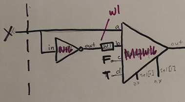
I realized that I had never used (until now) the Mux4Way16 in an implementation. I see that I got tripped up by the left-to-right, right-to-left in my Truth Table and my implementation. Not sure how I would know this form the Mux4Way16 specification?

I did a Google search "Mux4Way16" and the first page came up:

https://github.com/whostolebenfrog/The-Elements-of-Computing-Systems/blob/master/project1/Mux4Way16.hdl

I saw the sel[0] and sel[1] were the opposite of mine.

I understand the LSB is the right-most bit and the MSB is the right-most bit; I guess it's as simple as that.

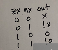
Now on to the zr, ng outputs...

Taking the incremental approach (thank you for exhortation!) I was able to tackle the zr and ng bits separately; and was able to implement successfully. It also helped to comment out the compare file in order to evaluate each output independently.

Thanks again for all those who helped me with all the chips/gates. I can now move on to Sequential Logic; one step closer to "Building a Computer from First Principles".
12