ALU Multiplexer

classic Classic list List threaded Threaded
5 messages Options
Reply | Threaded
Open this post in threaded view
|

ALU Multiplexer

mdantzis
If I understand correctly, the sel represents a binary number 0 or 1 for Mux…000-111 for Mux8Way16 and the Multiplexer outs the line the matches the binary number.

If this is correct the answers to a logical or mathematic functions truth table tells us what combinations of x, y, and switches produces a 1, and these 1 are encoded from 000 to 111(connected to a through h on Mux8Way16)) to match the x y and sel switches (the truth tables individual lines).

If all this is correct in Mux16, Mux4Way16 and Mux8Way16 the sel (switches e.g. ZX, NX…) is 1to 3 bits
but x and y are 16bits.

I know this can be done by brute force.

But must I repeat each ALU function 16 times?
 
There must be a better way to connect  x[16] and y[16] to sel in the multiplexer
Reply | Threaded
Open this post in threaded view
|

Re: ALU Multiplexer

cadet1620
Administrator
I don't understand. How are you wanting to connect the 16 wires in x or y to a 3-bit sel?

The only useful place you can connect x or y to on a MuxNway16 are the 16-bit inputs.
Hint: for the ALU you don't need anything wider than Mux16, but you can save a couple parts by using some Mux4Way16s.


--Mark
Reply | Threaded
Open this post in threaded view
|

Re: ALU Multiplexer

mdantzis


With this Mux16 would I have to And together the x, y and switches to output the 1 or zero?
If so wouldn’t  I need 16 Anding sets for each x[16] and y[16]?
Is there a better way?
Maybe I am mistaken to think that I load b=true and a=false, however if I load a=x and b=y I will
get the wrong output

thanks for the help
Reply | Threaded
Open this post in threaded view
|

Re: ALU Multiplexer

cadet1620
Administrator
Do not think of the ALU as a collection of functions that you need to implement individually.

If you follow the instructions in the book and the pseudocode in the ALU.hdl skeleton file you will build an ALU that does all the required operations.

/**
 * The ALU.  Computes a pre-defined set of functions out = f(x,y)
 * where x and y are two 16-bit inputs. The function f is selected
 * by a set of 6 control bits denoted zx, nx, zy, ny, f, no.
 * The ALU operation can be described using the following pseudocode:
 *     if zx=1 set x = 0       // 16-bit zero constant
 *     if nx=1 set x = !x      // Bit-wise negation
 *     if zy=1 set y = 0       // 16-bit zero constant
 *     if ny=1 set y = !y      // Bit-wise negation
 *     if f=1  set out = x + y // Integer 2's complement addition
 *     else    set out = x & y // Bit-wise And
 *     if no=1 set out = !out  // Bit-wise negation
 *
 * In addition to computing out, the ALU computes two 1-bit outputs:
 *     if out=0 set zr = 1 else zr = 0 // 16-bit equality comparison
 *     if out<0 set ng = 1 else ng = 0 // 2's complement comparison
 */
Since in HDL each signal needs a name, this pseudocode needs to be expanded to indicate the linear nature of hardware.

    if zx then
        x1 ← 0
    else
        x1 ← x
    if nx then
        x2 ← ! x1
    else
        x2 ← x1
    ...

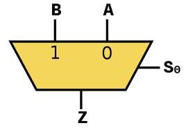
Muxes make choices so they are used to implement the if/then/else concept. The first if/then/else can be implemented as

    Mux16 (a=x, b=false, sel=zx, out=x1);


There is a worksheet that will help you see how the ALU computes the correct functions using this design.

--Mark

Reply | Threaded
Open this post in threaded view
|

Re: ALU Multiplexer

mdantzis
Thanks for the help.

I did the worksheet and it cleared up everything!
I was thinking it was software.

Great hints.

I have completed ALU.


Thanks