[Too brain dead to work today, so I've been "knitting" with
Logisim.]
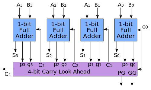
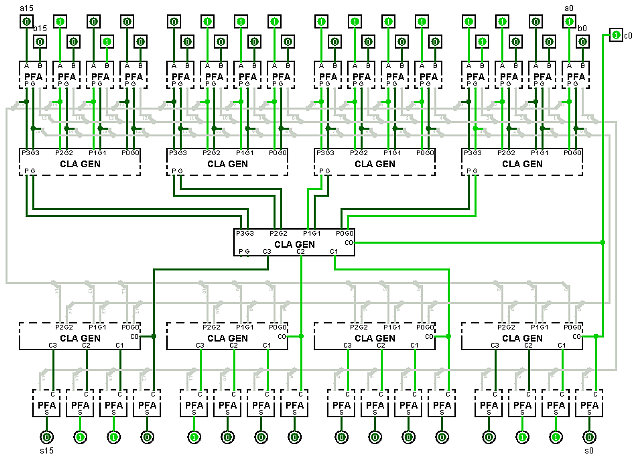
Here is the implementation of the 16-bit Carry Lookahead Adder, using lookahead at both levels.
The full adder used in the Carry Lookahead Adder is a special version called a Partial Full Adder (PFA). The PFA replaces the normal carry output from a full adder with the propagate and generate signals required for carry lookahead. 'p' is the first half adder's output and 'g' is the first half adder's carry.
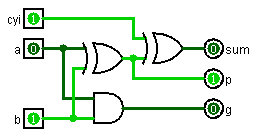
Note that I've split the PFA into its two stages so that you can see that the first stage outputs, 'p' and 'g', only depend on 'a' add 'b' inputs. Thus, the 'p' and 'g' inputs to the first level CLA generators do not depend on any of the internal carries.
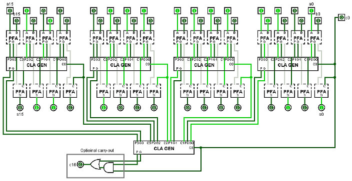 |
The gray wires are the internal connections between
the top and bottom halves of the PFAs. |
It's still rather hard to see how the internal carries are routed up to the second level CLA generator and back down to the first level. It still looks like there is a long path for the carries to be processed multiple times through the second level CLA generator as they go from right to left across the first level.
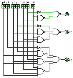
To understand why this isn't so, the first thing to realize is that the CLA generator is really two separate circuits: a lookahead generator and a carry generator.
The Lookahead generator takes the 'p' and 'g' inputs and generates 'pp' and 'gg' outputs. 'pp' and 'gg' can be implemented with two gate delays.
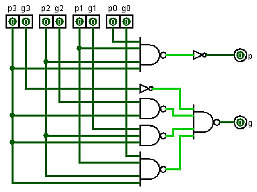
The carry generator takes the 'p', 'g', and 'c0' inputs (ignoring 'p3' and 'g3') and generates 'c1', 'c2' and 'c3'.
This next circuit shows the first level CLA generators as their two separate parts. Now you can see that the signal path in the adder moves strictly top to botom.
 |
The gray wires are the internal connections between the top
and bottom halves of the PFAs and CLA generators. |
Since the delay time for the half adders, the lookahead generator and the carry generator are all 2 gate delays, the 16-bit CLA adder can add with only 10 gate delays.
If you would like the Logisim circuit file, or just want to talk more about adders, please feel free to email me.
--Mark