About carry lookahead adder

classic Classic list List threaded Threaded
6 messages Options
Reply | Threaded
Open this post in threaded view
|

About carry lookahead adder

reflectionalist
This post was updated on .

I implemented Add16 using a combination of ripple carry and carry lookahead, that is, looking ahead carry in each 4-bit group while rippling carry between groups. Although I managed, the reason to divide the bits into groups is not quite clear to me. The text of the Wikipedia article on this is quite confusing:

The net effect is that the carries start by propagating slowly through each 4-bit group, just as in a ripple-carry system, but then move 4 times as fast, leaping from one lookahead carry unit to the next. Finally, within each group that receives a carry, the carry propagates slowly within the digits in that group.

The more bits in a group, the more complex the lookahead carry logic becomes, and the more time is spent on the "slow roads" in each group rather than on the "fast road" between the groups (provided by the lookahead carry logic). On the other hand, the fewer bits there are in a group, the more groups have to be traversed to get from one end of a number to the other, and the less acceleration is obtained as a result.

Is the last sentence of the first paragraph and the first sentence of the second paragraph quoted above correct? I think the "fast road" is inside a group while the "slow road" between groups.

Another question is about the picture of 4-bit carry lookahead adder in the Wikipediate article:

What are the PG and GG pins for in the picture?

Reply | Threaded
Open this post in threaded view
|

Re: About carry lookahead adder

cadet1620
Administrator
See this thread: Carry-Lookahead-Implementation

There are some forum posts on some other faster adder architectures:
    Carry Select Adder
    Carry Bypass Adder


The quoted text from Wikipedia appears to be describing a mixed ripple-carry/lookahead-carry adder, where 4-bit ripple-carry adders are used as primitives rather than the single bit adders shown in the picture.

The PG and GG outputs from the CLA block are so that 2, 3 or 4 CLA blocks can feed a second level CLA block that process the PG and GG from the first level.

For example, 4 16-bit CLA adders can be combined to make a 64-bit CLA adder.

--Mark
Reply | Threaded
Open this post in threaded view
|

Re: About carry lookahead adder

reflectionalist
cadet1620 wrote
The quoted text from Wikipedia appears to be describing a mixed ripple-carry/lookahead-carry adder, where 4-bit ripple-carry adders are used as primitives rather than the single bit adders shown in the picture.
Ah, right. So, to summarize, there are at least three ways to implement a 16-bit adder using 4-bit ripple-carry/carry-lookahead adders:
  1. Using ripple-carry in each 4-bit group, but carry-lookahead between groups (the way described in the Wikipedia article)
  2. Using carry-lookahead in each 4-bit group, but ripple-carry between groups (my implementation)
  3. Using 4-bit carry-lookahead hierarchically (where PG and GG are for)
Reply | Threaded
Open this post in threaded view
|

Re: About carry lookahead adder

cadet1620
Administrator
This post was updated on .
[Too brain dead to work today, so I've been "knitting" with Logisim.]

Here is the implementation of the 16-bit Carry Lookahead Adder, using lookahead at both levels.

The full adder used in the Carry Lookahead Adder is a special version called a Partial Full Adder (PFA). The PFA replaces the normal carry output from a full adder with the propagate and generate signals required for carry lookahead. 'p' is the first half adder's output and 'g' is the first half adder's carry.
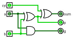
Partial Full Adder schematic

Note that I've split the PFA into its two stages so that you can see that the first stage outputs, 'p' and 'g', only depend on 'a' add 'b' inputs. Thus, the 'p' and 'g' inputs to the first level CLA generators do not depend on any of the internal carries.
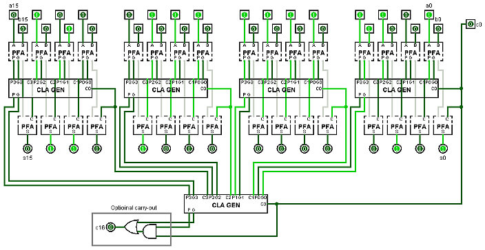
16-bit Carry Lookahead Adder schematic
The gray wires are the internal connections between
the top and bottom halves of the PFAs.

It's still rather hard to see how the internal carries are routed up to the second level CLA generator and back down to the first level. It still looks like there is a long path for the carries to be processed multiple times through the second level CLA generator as they go from right to left across the first level.

To understand why this isn't so, the first thing to realize is that the CLA generator is really two separate circuits: a lookahead generator and a carry generator.

The Lookahead generator takes the 'p' and 'g' inputs and generates 'pp' and 'gg' outputs. 'pp' and 'gg' can be implemented with two gate delays.
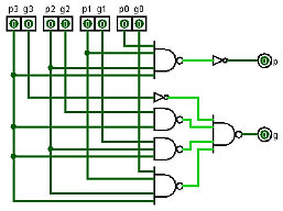
P and G generation for 4-bit CLA

The carry generator takes the 'p', 'g', and 'c0' inputs (ignoring 'p3' and 'g3') and generates 'c1', 'c2' and 'c3'.
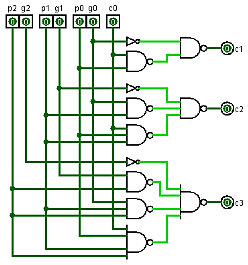
Carry generation for 4-bit CLA

This next circuit shows the first level CLA generators as their two separate parts. Now you can see that the signal path in the adder moves strictly top to botom.
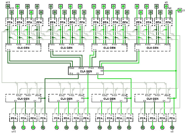
16-bit Carry Lookahead Adder with split CLA generator
The gray wires are the internal connections between the top
and bottom halves of the PFAs and CLA generators.

Since the delay time for the half adders, the lookahead generator and the carry generator are all 2 gate delays, the 16-bit CLA adder can add with only 10 gate delays.

If you would like the Logisim circuit file, or just want to talk more about adders, please feel free to email me.

--Mark

Reply | Threaded
Open this post in threaded view
|

Re: About carry lookahead adder

reflectionalist
This is awesome. Thanks for the demonstrations. I am going to try logisim. Correction to a minor typo:
cadet1620 wrote
The carry generator takes the 'p', 'g', and 'c0' inputs (ignoring 'p3' and 'g3') and generates 'c0', 'c1' and 'c2'.
The last three pins should be named 'c1', 'c2' and 'c3'.
Reply | Threaded
Open this post in threaded view
|

Re: About carry lookahead adder

cadet1620
Administrator
reflectionalist wrote
This is awesome.  Thanks for the demonstrations.  I am going to try logisim.  Correction to a minor typo:

cadet1620 wrote
The carry generator takes the 'p', 'g', and 'c0' inputs (ignoring 'p3' and 'g3') and generates 'c0', 'c1' and 'c2'.
The last three pins should be named 'c1', 'c2' and 'c3'.
Fixed.  Thanks for catching the typo.  Brain dead programmers always start counting at 0, it seems.  8-(

--Mark