Can't grasp DFF output |
||||||
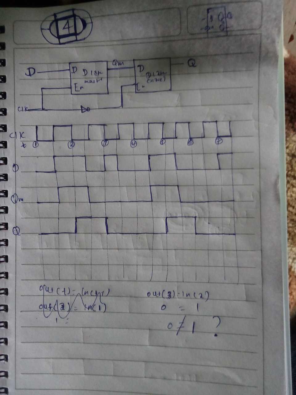
Can't grasp DFF output
Re: Can't grasp DFF output
Re: Can't grasp DFF output
Re: Can't grasp DFF output
Re: Can't grasp DFF output
|


| Free forum by Nabble | Edit this page |