|
|
|
|
I am making a counter but I am unsure how to put it together. I know that I need a register, a mux16, and the inc16. Any suggestions. I guess where it confuses me is in the aspect of incrementing. I am not sure just exactly how it does. Also, is there a truth table for this chip?
|
|
Administrator
|
If you are talking about the Program Counter part, the truth table, like most of the truth tables in this project, is given in the form of a functional description. Look at Figure 3.5 (in the 1st Ed).
|
|
|
Im not understanding the truth table with the (t-1) and so on.
|
|
Administrator
|
The (t-1) just refers to the last clock cycle. So x(t) is the value of signal x after the current clock cycle and x(t-1) is the value of signal x after the last clock cycle (i.e., the prior value of x).
|
|
|
I think Figure 3.5 is slightly confusing. My background with regard to functional notation is in mathematics where, in the expression x(t), the variable t refers to a specific input value and the evaluation of the function to produce an output value always results in a single number. In this case t, as the "input" to the function x(), must represent a particular point in time.
In the figure, the authors seem to use the numbers 22, 23, 24, ... to number the successive clock cycles, intervals of time, not a point in time. Yet in the discussion of Figure 3.5, they talk about "at time 23" or "until time 29", although the numbers seem to label intervals. It seems to me these references are meant to refer to a specific instant of time. This would be consistent with that way I use conventional functional notation and a statement like if reset(t-1) then out(t)=0 would be consistent functional notation. I realize that in certain high-level programming languages the term "function" has been co-opted to refer to a specific program construct. In the chip specification, is this the way the authors are using the idea of a function?
I understand, of course, that the diagram is idealized. The input and output values cannot instantly change at a point in time for real electronic devices. This probably adds to the confusion, as the graphs of the various time dependent function values, say reset() or out(), do not therefore represent the graphs of functions in the mathematical sense.
The clock graph is illustrating the continuous flow of time. Wouldn't it be appropriate to label the points on the clock depiction that correspond to the way that time is being described in the figure discussion? I think that time 22 occurs at the point of the first arrowhead in the diagram. The time 23 occurs at the point of the second arrowhead, and so on. Is this right?
|
|
|
Been a while since I took this course, but the way I see it, each clock cycle is a tick (low) and tock (high) sequence. The diagram shows a clock cycle beginning with the beginning of a tick (low) and ending at the end of a tock (high).
So clock cycle 23, for example, starts in a low phase of the clock, and then changes to a high phase and the cycle ends at the end of the high phase of the clock. Cycle 24 starts when the clock is low again.
Note the DFF is designed to be "positive edge triggered". Meaning, only when the clock transitions from low (tick) to high (tock) will the output of the DFF be impacted. The opposite is not true. If it transitions from high to low, the output is not impacted. Also, the DFF is not "level triggered" either, by which I mean to say the output is not impacted by the mere fact of the clock being high. Rather, the output is impacted by the transition from low to high.
|
|
Administrator
|
I don't see where it says that the DFF is designed to be positive edge triggered. Figure 3.5 is drawn consistent with either a negative-edge triggered DFF or with a DFF that captures the input one the rising edge and changes the output on the falling edge (the latter behavior is common with the simpler master-slave flip flop implementations).
The use of the notation x(t) and x(t-1) is fine from a mathematical perspective, particularly if you assume perfectly clean signals that change immediately and only at the clock edges.
If you want to imagine time being a continuous function, then you need to decide where on that figure a time of "22" corresponds. Is it the first black dot (so at the falling edge of the clock)? Is it the exact middle of a clock cycle (so at the rising edge of the clock?). Is it 7/39ths of the way between? Pick one and then be consistent.
So let's say that 22.0000... is the moment in time when that first black dot appears on the x-axis. What is out(30.216)?
First question we have to answer is what is reset(t-1), or reset(29.216)? It's 0, so we do go to the first else clause which looks at whether load(t-1), or load(29.216) is 1. It is, so then out(t) = in(t-1), or out(30.216) is whatever in(29.216) is and since in(29.216) is 527, out(30.216) is 527.
In real circuits, there is a region of uncertainty around the sensitive clock events. For a negative-edge triggered device (which this diagram is consistent with), we assume (we demand) that all of the signals at the inputs be established and stable a small amount of time before the clock edge (this is known as the setup time) and that they remain stable and unchanging until a small amount of time after the clock edge (this is known as the hold time). Just using made up numbers, let's say that we have a 1 MHz clock rate, so a full clock cycle is 1000 ns. We might have a set up time of 50 ns and a hold time of 20 ns. That's for the inputs. For the outputs, we have a minimum and maximum propagation delay, which is the amount of time it takes from when the clock changes (usually taken to be when it is halfway between states) to when the output changes. For our mythical device, the minimum propagation time has to me more than 20 ns (i.e., the hold time requirement) because if it isn't, the changing output from one DFF could violate the hold time requirement of whatever DFF follows it. The maximum propagation delay will determine how short our overall clock cycle can be (i.e., the maximum speed at which we can clock the chip) without violating the next DFF's setup requirement for the next sensitive clock edge.
In this idealized system, none of this matters because we assume that everything changes instantaneously at the clock edge and, furthermore, we never care what the signals happen to be at exactly those moments in time since the signals will be fully defined an infinitesimal amount of time either before or after the clock edge. When we are AT the clock edge and a signal is changing, all we know is that it is somewhere between the two.
The better way to think about sequential logic is, assuming setup and hold time requirements are met, the output a short time after the clock edge is dictated by the inputs a short time before the clock edge.
|
|
|
oops sorry about that. I had a vague memory of input changes only being reflected in the simulator when going from tick to tock, making me assume it was positive edge triggered.
|
|
Administrator
|
And that may be -- I recall there being some inconsistent behavior that I wanted to delve into. I'm not even sure why they bother with tick and tock as far as making information available to the user. I suspect internally that they are emulating the DFF implementation as a level-triggered, biphase master-slave design, but to the user it really doesn't matter.
|
|
|
You state that “the notation x(t) and x(t-1) is fine from a mathematical point of view”, but I respectfully disagree. Let’s assume that x() is the function reset() that is used in the PC chip specification. Further, we must assume that this function is defined only for non-negative integers since only integers are available in the computer at the hardware level as inputs to the function. (Really only arrays of 16 bits which we can think of as non-negative integers.) So, we can eliminate computing the value of reset(29.216). We can’t pass the value 29.216 to the function, so we can’t compute that (undefined) value of the function.
The only thing we have which defines the value of reset(t) is the graph provided in Figure 3.5.
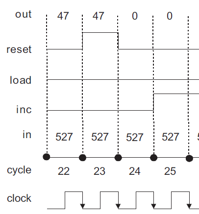 So, what is the value of reset(23) based on the graph that is presented? Is it 0 or is it 1? Is it the value at the beginning of cycle 23 or at the end of cycle 23? Oh wait, the graph shows it has every value between 0 and 1 (inclusive) at the beginning and end of the cycle. I assure you that in mathematics, functions must evaluate to exactly one value for any input value (or values) at which they are defined. With the graph shown as the only definition of the values of reset(), it’s not a function in the mathematical sense.
Of course, your excellent description of what’s going on in a real device explains how a graph of the actual reset() signal levels would not have the “jump” in value at the beginning or end of a clock cycle. If the reset() signal value were accurately drawn versus time (as by an oscilloscope), it would look like the graph of a function: single valued at every time point. I assume the authors did not think this relevant or too complicated to use in the context here.
We can probably consider time to be relatively continuous as computers cannot yet operate at a cycle rate anywhere near the Planck time.
|
|
Administrator
|
x(t) is a function of TIME. It is not some piece of code that we pass a 16-bit integer to. The reset signal is a logic level (or, in the real world, a voltage level), but the independent variable is the continuous parameter of time.
Go back and read what I wrote about the value at the transitions in the idealized case depicted here. We don't know what they are at that moment and could simply eliminate the vertical part of any transition and declare the value at the transitions to simply be unknown or to be a 0, or a 1, or halfway in between, or whatever it was an incremental amount of time before. If you were concerned with any form of conservation laws, you could interpret that vertical edge as being a Dirac delta function of sufficient magnitude to cause a step change in the signal at the boundary. All of those choices have the same effect because, in treating t as a continuous variable, we simply don't care what it is or is not at the finite point in time corresponding to clock cycle boundaries.
Even when you start looking at signal delays and propagation paths and glitches that exist in real systems, you can continue to use this view as long as all of your logic is fully synchronous. What matters is that you know that any signal that transitions from one level to another across a clock cycle boundary is going to have a small window of time around that boundary where it's perceived level is indeterminate (or, more to the point, stochastic) -- and it is your responsibility to design the system so that it never attempts to do so or that, if it does, any effect is insignificant (this is one of the big reasons why Gray code counters are used in many applications, particularly asynchronous systems).
But while this view is valid, a much better view is to treat time as a discrete variable, in which most authors would write it as x[t] instead of x(t), but plenty of people, even mathematicians, use x(t) for both in situations in which it isn't necessary to use both concepts and carefully distinguish between them. An even more strict notation would be to write it as x[n] where n = floor(t/T) where T is the clock period. But making this fine a distinction really only has utility if you are treating the signal as a sampled data signal that you are going to do some kind of digital signal processing on -- that just isn't the case here.
It is more than adequate simply declare that the value of x(t) from shortly after a clock boundary until shortly after the next clock boundary is a function of the controlling signals just before the clock boundary and that signals don't change outside of the small window of time at the clock boundary. Given that constraint (a necessary constraint in any fully synchronous machine design), then the value of a signal just before the current clock boundary is the same as the signal just after the previous clock boundary, which is therefore x(t-1).
Note that the very fact that we are subtracting '1' from t means that t has to have the same units as the '1' and since the meaning of that 1 is 1 clock cycle, that means that t has to have the same meaning -- underscoring why it really should be expressed as x[n] where n is the number of clock cycles since some reference datum. But this does not mean that t has to be an integer -- it makes perfect sense to talk about the value of a signal at 29.216 clock cycles after the datum.
|
|
|
I'm not really concerned about x(t). I can't find an instance of this terminology at all in the book's 2nd edition. I'm sorry now I even brought it up. It's not needed to determine how to construct the logic for the PC chip. What is needed, however, is how to determine the time dependent output value of the so-called function reset(). To set the out(t) value of the chip at time t you need the signal level at reset(t-1). I don't think it's at all clear from Figure 3.5 how to do this if you're sampling the signal at the clock boundary. Again, I realize that this is an idealized view of what is actually going on, that the real circuits do not behave this way.
If the domain of reset() consists not of continuous time, but of sequentially numbered time intervals, then the graph kind of makes sense. From the diagram that means reset(23) == 1 and therefore out(24) == 0 because the if reset(t-1) then out(t) =0 is "executed". We can conceptually then forget completely what the signal is actually doing at the clock boundaries. That becomes a problem for the EE's and computer hardware engineers who are implementing the logic.
The next to last paragraph of your most recent post is a terrific answer in the real world to the original question posed in this chain. It's how I always understood the situation, and I think it can be used to decide how to process the signals that are inputs to the load(), inc(), and reset() "functions" given in the PC chip's functional specification.
I'm sure you have noticed that the authors have changed their notation a "bit" (npi) in the 2nd edition of their book to use the t and t+1 notation for sequential circuit specifications. Although this technically doesn't make any difference, it seems to me that it is more sensible for most people.
The diagram you referred to as Figure 3.5 of the 1st edition has been completely eliminated from the 2nd edition. The new Figure 3.5, which now appears in the section on the operation of the Bit chip, is similar to the previous diagram, although it is much simpler since it has no "reset" or "inc" signal inputs, and it eleminates a depiction of the clock itself.
There is also information in Section 3.3.4, Usage of the 2nd Edition which might be significant in designing the logic for the PC which I could not find in the 1st Edition. This is not exactly obvious, but certainly affects the operation of the if...else if...else conditional statement used to specify the functionality of the chip.
I think the 2nd edition of the book represents a general improvement. Even though it may not exactly match the flow of the Nand2Tetris MOOC, I would recommend it over the earlier edition.
|
|
Administrator
|
I would agree that the 2nd Ed is an improvement over the 1st (and I think the first was a very solid text for a first edition).
One thing that I was hoping they would simplify is the PC part. There is NO need for an inc signal at all. There is no instance when you want or need the PC to merely hold its current value.
If reset is HI, you reset; else if load is HI, you load; else you increment.
|
|
|
I'm just looking to find a truth table so I can create the chip. I figured if I have one I can create the chip based on the truth table. Understanding it is clocked did confuse me a little. I needed a simple: if 1 = 0 and so on. I understand it is 16 bit which in a way would be a gigantic truth table. I guess I'm left in the dark as to what the load will accomplich, the Inc, and the reset. I think if I assert load it will load a 16 bit register, Inc is confusing, and if I assert reset that will clear. ?
|
|
|
Problems: I am unable to peice together multiple chips.
Mux 16
16 bit register
So on.
Any suggestions?
|
|
Administrator
|
A truth table, per se, is for combinatorial logic, not sequential logic.
For sequential logic, things need to be defined in terms of behavior.
For the PC chip:
IF the reset signal is HI, THEN
the next value written to the PC's internal register is zero.
ELSE
IF the load signal is HI, THEN
the next value written to the PC's internal register is the value at the data input port.
ELSE
IF the inc signal is HI, THEN
the next value written to the PC's internal register is one greater than the current value stored there.
ELSE
the next value written to the PC's internal register is the value that is already there (i.e., it doesn't change.)
|
|
Administrator
|
Approach it incrementally.
First, implement a stripped down version of the PC that only has a reset input and if the reset input is HI, the internal register should become 0, while if the reset input is LO, the internal register shouldn't change. Implement that much.
Then add in another feature. Then another.
You don't have to start with reset, either. You might start with a counter that always increments. Whatever the current value stored in it, it will always increase by one each clock cycle. Once you have that, modify it to add one new feature at a time.
|
|
|
For the logic given, isn't it important that only one of reset. load, or inc be asserted during any clock cycle and the other two be LO, or is this obvious? Should the circuit logic insure that only one of these three signals can be HI during any cycle?
In the 2nd edition of the book, the authors specify this explicitly in the Usage note in Section 3.3.4 that provides the specification for the PC.
|
|
Administrator
|
In the first edition, the specification explicitly gives priority to the reset over the other two. If the reset is LO, then it gives priority to the load over the inc.
Notice that, in Fig 3.5, that inc is inserted before, during, and after the load pulse.
I haven't seen that part of the 2nd edition, but it sounds like they took a specification that was already more complicated than it needs to be and made it even more complicated.
The PC really only needs two inputs, reset and load, with reset taking priority over load. If neither is asserted, then the PC advances. There's no use case where you need the PC to hold its value from one cycle to the next (at least not that can't be accomplished via reset and/or load).
|
|

