in a quick scan through
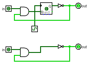
Code I only saw self-connected Nots in two places in chapter 14, both in theoretical context. Is there another place?
In the real world you need 3 Nots in series to make this work reliably.
Real digital ICs are, at heart, analog circuits. Functionally a Not gate is a very high gain inverting amplifier. It's output (transfer function) can be approximated as
Vout = C (1 - Vin)
where C is a large constant. The actual transfer function is non-linear and depends on the type of logic.
When you connect the output of a Not gate to itself, you have created an analog computer that is solving for Vout = Vin. The idealized transfer function above has the solution Vout = Vin = 0.5. Real world parts settle to somewhere between 0 an 1.
7400 series TTL tolerates this mid-level voltage, but for 4000 series CMOS, this is really bad news because both of the output transistors are turned on at the same time and a large amount of current flows through the gate and can result in burnout.
(4000B series added output buffers after the gates. The output buffers are effectively 2 inverters in series so there are 3 inverters in each of the Not gates in the part. Connecting a 4049B's output to it's input may work as an oscillator since it is physically 3 inverters in series.)
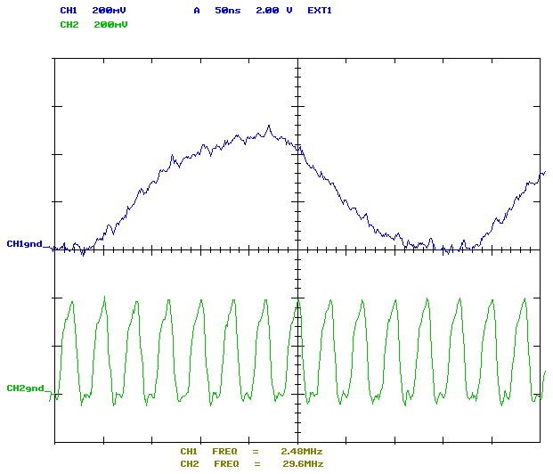
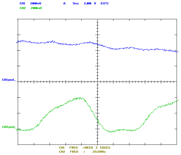
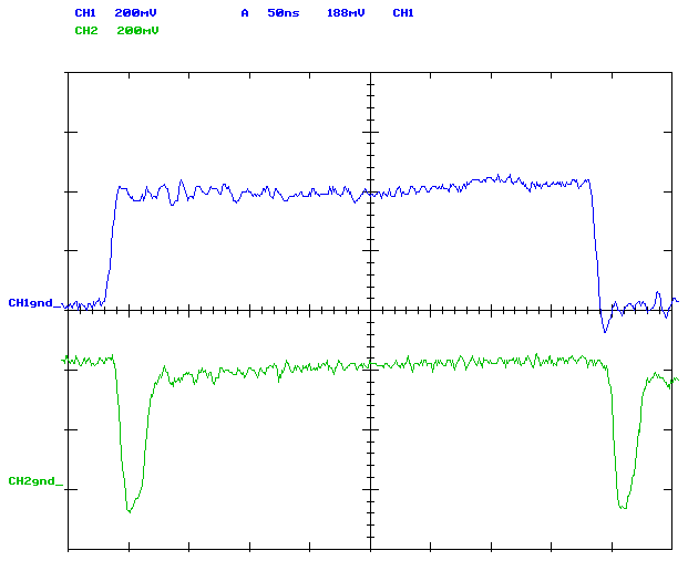
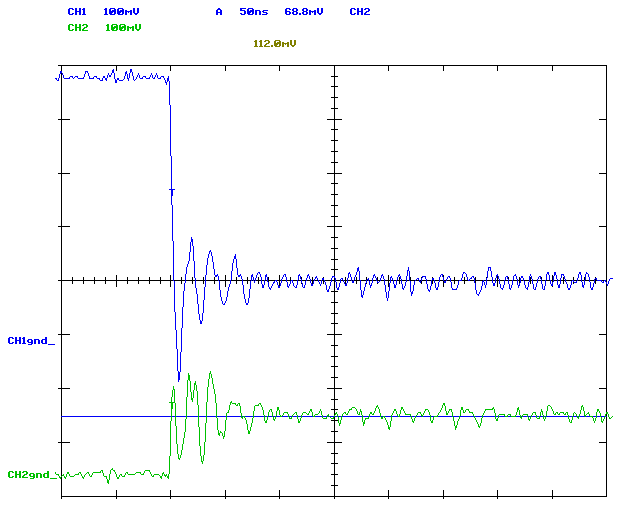
Even though you can get 3 Not gates to reliably oscillate, you would not want to use this in real design. The propagation delay for ICs varies from batch to batch so the oscillation frequency will as well. In the real world, for frequency determination you need to include at least a resistor and a capacitor in the circuit, or better yet, a crystal.
The other major problem is that because the oscillation period (1/f) is close to the propagation delay of the ICc, the output is more like a sine wave than a square wave.
|
3-Inverter oscillators
top: 4000 series CMOS
bottom: 74LS00 series TTL
(Use your browser's "view image" to see the full sized images.)
|
These slow rise times are good enough to feed a TTL flip-flop or counter, but I've never tried it with CMOS which generally has problems with slow rise times.
--Mark