Desmond.Song wrote
I have two question flowing:
1. “0+”, “1+”, “2+” is a high level or a rising edge ?
The "out" value is change at “0+”, “1+”, “2+” rising edge or not ?
2. If “0+”, “1+”, “2+” is a high level state, what the value of the out should be when the “0+”, “1+”, “2+” is in a low level, hold the value before or not?
Who can help me , sorry for my poor English, thanks in advance!
This is confusing because clock "edges" and "levels" are part of the
physical implementation of sequential logic, not part of the logical implementation. In the logical abstraction, you should think of the clock as a periodic
event.
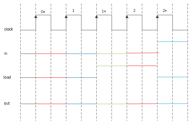
In the drawings in the book and the lecture slides, the physical clock is shown as falling edge triggered. See figure 3.5, for example.
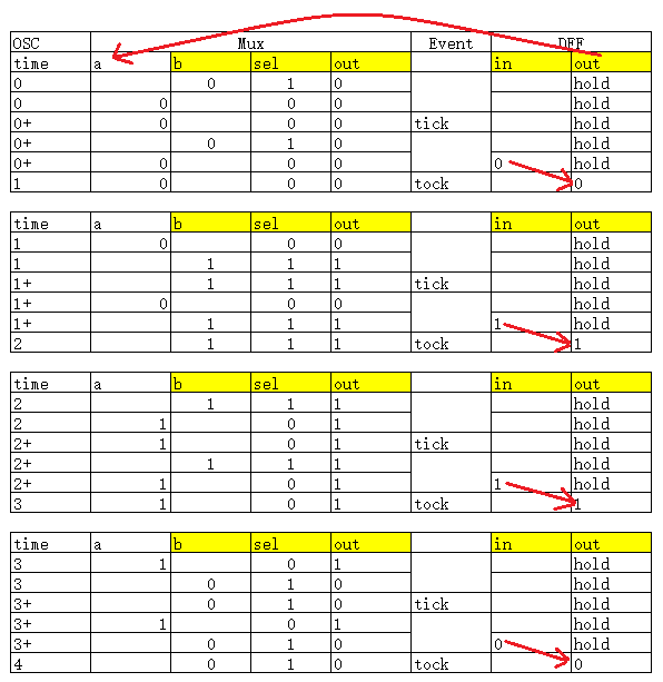
In the Hardware Simulator, "tick" and "tock" are events. "tick" occurs in the center of a clock period, and "tock" occurs between time periods.
"tock" is the abstract clock event that triggers the sequential logic.
At the "tick" command, combinational logic is evaluated, but sequential logic is not updated.
The time changes from (
n) to (
n)+.
At the "tock" command, combinational logic is evaluated, and sequential logic is updated.
The time changes from (
n)+ to (
n+1).
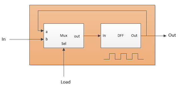
Here's an HDL and test script that exposes the signal between the Mux and the DFF and soes extra outputs after the "set" commands that change the "in" and "load" inputs. It better shows when things are changing.
BitX.hdl BitX.cmpHere's the test output, with some notes.
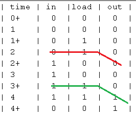
| time | in  |load |dffin| out |
    initial values
| 0    |  0  |  0  |  0  |  0  |
    not loading a 1
| 0    |  0  |  1  |  0  |  0  |  set, eval, output;
| 0    |  1  |  0  |  0  |  0  |  set, eval, output;
| 0+   |  1  |  0  |  0  |  0  |  tick, output;
| 0+   |  0  |  1  |  0  |  0  |  set, eval, output;
| 0+   |  1  |  0  |  0  |  0  |  set, eval, output;
| 1    |  1  |  0  |  0  |  0  |  tock, output;
    loading a 1
| 1    |  0  |  0  |  0  |  0  |  set, eval, output;
| 1    |  1  |  1  |  1  |  0  |  set, eval, output;
| 1+   |  1  |  1  |  1  |  0  |  tick, output;
| 1+   |  0  |  0  |  0  |  0  |  set, eval, output;
| 1+   |  1  |  1  |  1  |  0  |  set, eval, output;
| 2    |  1  |  1  |  1  |  1  |  tock, output;
    not loading a 0
| 2    |  1  |  1  |  1  |  1  |  set, eval, output;
| 2    |  0  |  0  |  1  |  1  |  set, eval, output;
| 2+   |  0  |  0  |  1  |  1  |  tick, output;
| 2+   |  1  |  1  |  1  |  1  |  set, eval, output;
| 2+   |  0  |  0  |  1  |  1  |  set, eval, output;
| 3    |  0  |  0  |  1  |  1  |  tock, output;
    loading a 0
| 3    |  1  |  0  |  1  |  1  |  set, eval, output;
| 3    |  0  |  1  |  0  |  1  |  set, eval, output;
| 3+   |  0  |  1  |  0  |  1  |  tick, output;
| 3+   |  1  |  0  |  1  |  1  |  set, eval, output;
| 3+   |  0  |  1  |  0  |  1  |  set, eval, output;
| 4    |  0  |  1  |  0  |  0  |  tock, output;
All of the changes to "in" and "load" are caused by "set" commands in the test script. They show that the value of "dffin" does not affect the DFF except when the "tock" command occurs.
--Mark