How the feedback is evaluated internally in BIT

classic Classic list List threaded Threaded
7 messages Options
Reply | Threaded
Open this post in threaded view
|

How the feedback is evaluated internally in BIT

Thorvald
I understand that to load, or recall, a bit you need the diagramof Fig. 3.1. What I still does not understand is what happens behind the curtain. My implementation is

 Mux(a=outDFF, b=in, sel=load, out=inDFF);
 DFF(in=inDFF, out=outDFF, out=out);

(Sorry for posting the answer, but it has to be done so I can work out my question).

So what happens at the beginning is that it is evaluated the mux gate, but c'mon, we don't have an initial value in outDFF, so how is this value taken into account???

After that, it just go looping around this two gates, but how this is done? I mean, I would like to see a for or while loop to execute those gates a number of t-times, right?
Reply | Threaded
Open this post in threaded view
|

Re: How the feedback is evaluated internally in BIT

cadet1620
Administrator
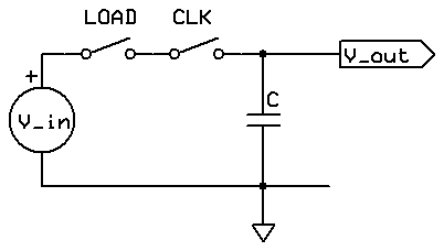
[I don't worry about including the implementation of Bit.hdl; it's exactly Fig. 3.1 translated to HDL.]
Thorvald wrote
    Mux(a=outDFF, b=in, sel=load, out=inDFF);
    DFF(in=inDFF, out=outDFF, out=out);

So what happens at the beginning is that it is evaluated the mux gate, but c'mon, we don't have an initial value in outDFF, so how is this value taken into account???
In the n2t hardware simulator, DFFs come up in state 0 at time t=0.

In the real world, when you apply power to a DFF it comes up in a valid state, either 0 or 1, but you do not know which. The hardware designer needs to guarantee that the circuit will be set to a known state by a 'reset' signal that occurs shortly after power-up.

For instance, you could add a reset to the DFF like this
    Mux(a=outDFF, b=in, sel=load, out=next);
    Not(in=reset, out=notReset);
    And(a=notReset, b=next, out=inDFF);
    DFF(in=inDFF, out=outDFF, out=out);
Usually, though, resets are handled at a higher level in the logic, as they are in the Hack computer's PC chip.
After that, it just go looping around this two gates, but how this is done? I mean, I would like to see a for or while loop to execute those gates a number of t-times, right?
It might help to think of sequential logic as an animated movie, rather than a software loop.

The paper starts blank.
The animator updates the scene based on the script (inputs and current state of the DFF).
Press the camera's shutter button to photograph the scene (clock tick updates DFF).
The animator updates...

If you want to look at what happens inside the DFF, visit
    http://play-hookey.com/digital/sequential/d_nand_flip-flop.html
You can click on the D and CLK inputs.
There is lots of great information on this site.


--Mark
Reply | Threaded
Open this post in threaded view
|

Re: How the feedback is evaluated internally in BIT

Thorvald
Ok, so it's really like under the order of tick and tock the two gates are evaluated over and over again (like in a while determined by the time), right?

Another doubt around the same issue: I notice that the Register and Ramn has input and output with crossed arrows, this really means that sometimes we don't want to input but output something and viceversa, right? (sorry I'm a physiscist)

So there should be a control unit above it that says to the register, hey, load something but do not output something, correct?

In any case, if I want to output the contents of my register, should I put some garbage at the input and set load=0?
Reply | Threaded
Open this post in threaded view
|

Re: How the feedback is evaluated internally in BIT

cadet1620
Administrator
Thorvald wrote
Ok, so it's really like under the order of tick and tock the two gates are evaluated over and over again (like in a while determined by the time), right?
The combinational logic gates are evaluated continuously. Like an audio amplifier, changes on the inputs are continuously reflected on the outputs.
Another doubt around the same issue: I notice that the Register and Ramn has input and output with crossed arrows, this really means that sometimes we don't want to input but output something and viceversa, right? (sorry I'm a physiscist)
The diagonal line on the input and output signals indicates that those signals are buses, and the number next to the diagonal is the number of bits in the bus. The outputs of N2T Registers and RAMs are always driven; you don't need to do anything to the input data to get output data.
So there should be a control unit above it that says to the register, hey, load something but do not output something, correct?

In any case, if I want to output the contents of my register, should I put some garbage at the input and set load=0?
Remember back to first year physics, basic electricity.  This is the analog equivalent to a Bit:

    analog sample-hold
The voltage on the capacitor can always be measured, but the input can only charge/discharge the capacitor when both 'load' and 'clock' are on.

--Mark
Reply | Threaded
Open this post in threaded view
|

Re: How the feedback is evaluated internally in BIT

Thorvald
Thank you for the circuit diagram, this is helpful. I lost a bit (haha a bit :) ).
Reply | Threaded
Open this post in threaded view
|

Re: How the feedback is evaluated internally in BIT

ron2308
Hello Mark,
I couldnt reach the play-hookey.com site.
It seems that it is not valid any more.
is there any other site you can refer me to?
Thanks,
Ron Levy
Reply | Threaded
Open this post in threaded view
|

Re: How the feedback is evaluated internally in BIT

WBahn
Administrator
Sadly, Mark is no longer with us.

Wikipedia has a pretty decent article on how a DFF works.

https://en.wikipedia.org/wiki/Flip-flop_(electronics)

You might give that a go.