Initial value of DFF

classic Classic list List threaded Threaded
8 messages Options
Reply | Threaded
Open this post in threaded view
|

Initial value of DFF

bikal
It is said that DFF out parameter outputs the previous value (t-1). What is the value of DFF at time 0? Undefined?
Reply | Threaded
Open this post in threaded view
|

Re: Initial value of DFF

WBahn
Administrator
In general it is unknown (this is especially true in the real world). However, I believe this simulator initializes all DFFs to LO. But you should avoid designs that rely on this.
Reply | Threaded
Open this post in threaded view
|

Re: Initial value of DFF

bikal
This post was updated on .
In chapter 3, we use a mux and a dff to implement a 1 bit register. Looking at the schematics, it seems the circuit is recursive,

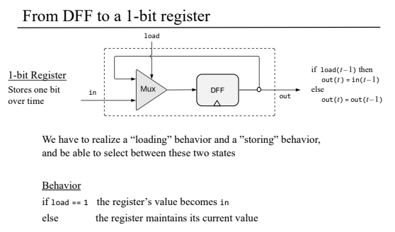
IIUC, the input to the mux is the output of DFF, and the input to the DFF is the output of mux. Which one is initialized first and with what value?

I will guess and assume it is the DFF at 0+ time with value 0. After which the circuit can move on to evaluating the mux gate and again the DFF gate. Such that at  't = 1' we get the output of whole 1 bit register. Is my understanding correct? i.e. the whole 1 bit register is evaluated within the 1 clock cycle (tick and tock).

The other question: if DFF out at t=0 is not know in real world, how does the mux gate ever get evaluated? Does it not require the out value from DFF to be evaluated successfully?
Reply | Threaded
Open this post in threaded view
|

Re: Initial value of DFF

WBahn
Administrator
Let's say that the initial value of the DFF at power-up is X, which is either 0 or 1, but which we do not know. But it IS one or the other, we just don't know which.

As long as the 'load' signal to the register is 0, we will continue to store X, whatever it is, into the DFF. The circuit knows the value of X -- it's either a 0 or a 1, but it is one of them.

The first time we take 'load' HI (make it 1), now it doesn't matter what X is because the Mux will have as it's output the value on 'in', regardless of what the value of X happens to be, and that is the value that will get written into the DFF. If we know what the value at 'in' was, we now know what the value of 'out' will become on the next clock cycle.

So all we need to do is make sure that whatever circuit we use our 1-bit register for that we assert the 'load' signal, with a known and proper value at the 'in' pin, before we care about what the value at the 'out' pin is.
Reply | Threaded
Open this post in threaded view
|

Re: Initial value of DFF

bikal
WBahn wrote
So all we need to do is make sure that whatever circuit we use our 1-bit register for that we assert the 'load' signal, with a known and proper value at the 'in' pin, before we care about what the value at the 'out' pin is.
Ah yes, of course.  In real circuits we usually(always?) write the value to the register before trying to read it. Yep, this makes sense now. Thanks for your explanation.
Reply | Threaded
Open this post in threaded view
|

Re: Initial value of DFF

ashort
In reply to this post by bikal
indeed the 1 bit Register has a feedback loop, because of how the Mux and DFF are connected (the output of the DFF feeds into the Mux, and the output of the Mux feeds into the DFF).

Note that although the DFF chip is implemented for you in this course, you can design a positive edge triggered DFF yourself using, as one example, simple gates like Not, And, Nor, and a clock signal.  But you would need to arrange those gates using feedback loops to make the DFF work as intended.  So the DFF itself has its own feedback inside of it.
Reply | Threaded
Open this post in threaded view
|

Re: Initial value of DFF

WBahn
Administrator
If this were a true Nand-2-Tetris course, the authors would have had the DFF built up out of Nand gates as well. A positive-edge-triggered DFF can be constructed using five 2-input Nand gates and one 3-input Nand gate. But this is an example of a "fundamental mode" circuit and would arguably have been getting too far into the weeds for the goals of the course. More to the point, the current hardware simulator can't handle fundamental mode circuits and making one that can is a significant jump in complexity.
Reply | Threaded
Open this post in threaded view
|

Re: Initial value of DFF

WBahn
Administrator
In reply to this post by bikal
bikal wrote
Ah yes, of course.  In real circuits we usually(always?) write the value to the register before trying to read it. Yep, this makes sense now. Thanks for your explanation.
We don't always write before trying to read, but if we don't we need to consider carefully what the implications are. I've worked with free-running counter designs that have a 50/50 chance of powering up and running backwards. Instead of adding the complexity to be able to force an initial known state into all of the DFFs that made up the counter, we used a single gate at the junction between two counters that, when the counter rolled over (which it WILL do, regardless of which direction it's running) would have the effect of reversing the direction of the counter if it happened to roll over the wrong way. Thus, even though we had no idea of which state the counter powered up in or whether it was running forward or backward, we knew that it would be running the correct direction within one period of the counter, which was a matter of a few milliseconds. After that, everything would work find because everything else on the chip was synched to the counter states. But we did have to carefully evaluate the design to ensure that nothing catastrophic would happen during that initial period when things were very poorly defined.