Is the diagram for 'bit' on page 43 the wrong way around?

classic Classic list List threaded Threaded
7 messages Options
Reply | Threaded
Open this post in threaded view
|

Is the diagram for 'bit' on page 43 the wrong way around?

Jeroen
The moment I came across the 'bit' diagram on page 43 (chapter 3) it struck me as incorrect. As no one has mentioned it I am probable wrong, but according to page 21 (chapter 1) on a Mux a is the top pin and b is the bottom pin. When sel is '0' then out = a, when sel = '1' then out = b.

If we apply that logic to the 'bit' diagram then setting load to '1' will return te stored value and not load the value specified in 'in'.

I verified my logic with the hardware simulator.

Please tell me why I am wrong
Reply | Threaded
Open this post in threaded view
|

Re: Is the diagram for 'bit' on page 43 the wrong way around?

ybakos
Your opinion is valid. But the diagram of the Mux shown on page 43 is just an abstraction, and doesn't exactly correspond to the one you built. That said, consider the Mux shown on page 43 as "flipped upside down" with the load/sel signal on top, rather than on the bottom as shown on page 21 fig. 1.9
Reply | Threaded
Open this post in threaded view
|

Re: Is the diagram for 'bit' on page 43 the wrong way around?

Jeroen
That is one of the things I considered. Is there some kind of convention where the location of the sel 'line' determines which pin is a?
Reply | Threaded
Open this post in threaded view
|

Re: Is the diagram for 'bit' on page 43 the wrong way around?

cadet1620
Administrator
Industrial schematics usually use a symbol like this for multiplexers. (In this case, an 8-to-1 mux.)
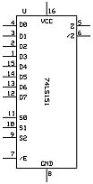


When a "shape" symbol is used, it is usually a trapezoid. The sel can be on either top or bottom. The a or D0 input is usually at the top. The inputs are often labeled to avoid confusion. For wider than 2-to-1 muxes, it is common to only label the a or D0 input. This is the TECS Mux8Way16 symbol I use. The '/' indicates a bus and its width.


--Mark
Reply | Threaded
Open this post in threaded view
|

Re: Is the diagram for 'bit' on page 43 the wrong way around?

Jeroen
Thanks Mark,

That is the sequence I have been using in my head, which is why I was so confused by the 'bit' diagram. I kept re-reading the part about (t-1) and I thought I was just missing something.

Personally I think the diagram in the book / PDF needs to be updated, but as I am the first person to publicly complain about this it doesn't appear to be a major issue.

Loving this course BTW. I have been developing software for 28 years (since I was 12), but I always wondered how things worked at the sub-assembler level.
Reply | Threaded
Open this post in threaded view
|

Re: Is the diagram for 'bit' on page 43 the wrong way around?

espressomakerdeluxe
Thank you for clarifying this. This also confused me in the Unit 3.2 video at 13:04, where the Flip Flop Mux load bit is shown as 0. It is likely the same diagram from the book.
Cheers.
Reply | Threaded
Open this post in threaded view
|

Re: Is the diagram for 'bit' on page 43 the wrong way around?

WBahn
Administrator
This post was updated on .
I wish the authors had named the input bits dn...d0 instead of alphabetically. Similarly, name the select bits sn..s0. Then you can consider the select bits to be a binary number that corresponds to the data input that is selected.

But that's not relevant to interpreting a schematic that doesn't have any labels. In that case, what the authors should have done is put some kind of indicator (a small circle is very common) on the part indicating the input that is selected when all of the select bits are LO. The rest of the inputs then proceed in order from there. That allows the order of the pins (top to bottom or bottom to top) to be independent of whether the sel pins are drawn on the top or the bottom, which gives the person drawing the schematic the flexibility to choose whichever way will result in cleaner schematic.

The diagram you are referring to requires the reader to infer the specific Mux connection based on the text referring to it -- which is not the best way to do things. The schematic should be unambiguous.