// This file is part of www.nand2tetris.org
// and the book "The Elements of Computing Systems"
// by Nisan and Schocken, MIT Press.
// File name: projects/1/Mux4Way16.hdl
/**
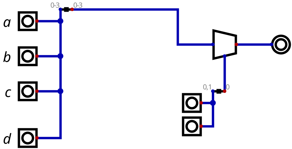
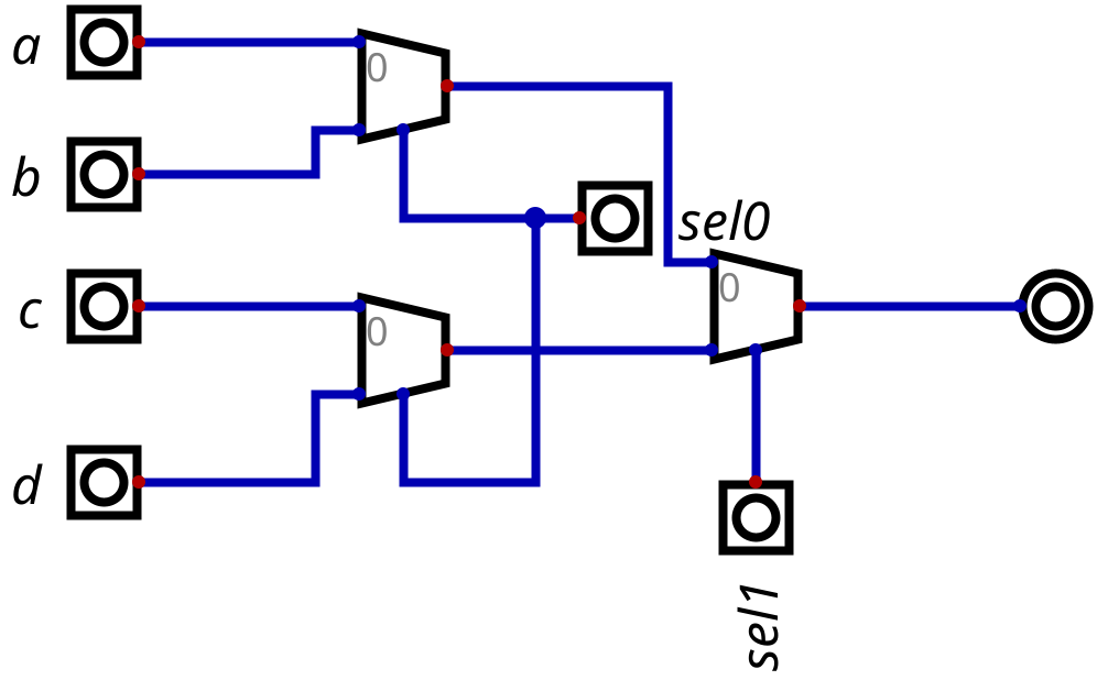
* 4-way 16-bit multiplexor:
* out = a if sel = 00
* b if sel = 01
* c if sel = 10
* d if sel = 11
*/
/**Algo for building gates:
1. Understand Truth table
2. Do logical flow of BITS with basic logic or previously built logic gates.
3. Fix portion/ story paragraph by paragraph with testing and comparing with output to Truth table desired.
4. Test final 'out' result. Fix any bug in flow of bits logic.
5. NB: for each paragraph of code draw the truth table and check if the output gives the correct answer for all possibilities of input pins.
6. NB: Check code paragraph as written not as you wish it or assume it eill work.
**/
CHIP Mux4Way16 {
IN a[16], b[16], c[16], d[16], sel[2];
OUT out[16];
PARTS:
////And, Or, Not, Xor, Mux, Mux16, And16, Or16, Not16
//// Replace this comment with your code.
//00. outand7=0. This code is wrong as 00, 10, 01 will give 1 as output.
//Algo:
//Good.
/**
So, what could you do to get a signal that is 1 if and only if sel[0] and sel[1] are 0.
Hint, think about how you would say it if you could only describe it in English using 1 (and not 0) in your description.
For instance, you can say, "If x is 0", but you can say, "If x is not 1". You also can't use terms like "both" or "either",
but you can say things like, "If (thing) and (something)", or, "If (something) or (something)".
So translate the statement "If both sel[0] and sel[1] are 0" into an equivalent sentence subject to the above constraints.
Spoiler. To some degree, this discussion is going down a bit of a rabbit hole because there is a very simple way to implement this chip,
based on the cereal dispenser analogy I gave above. None-the-less, it looks like it will still be worthwhile to help you build your reasoning
skills regarding digital logic.
*/
/*
Algo to determine sel[2]=00 : IFF BOTH sel[0]=0 and sel[1]=0 return 0, that is true:
problem: sel[0]=1 and sel[1]=1 will also return 1
sel[0]=0 and sel[1]=0 will also return 1
Truth table:
a b And Or Nor Xor ? ?
0 0   0  0   1     0 1
0 1   0  1   0   1 0 1
1 0   0  1   0   1 1 0
1 1   1  1   0     0 1
*/
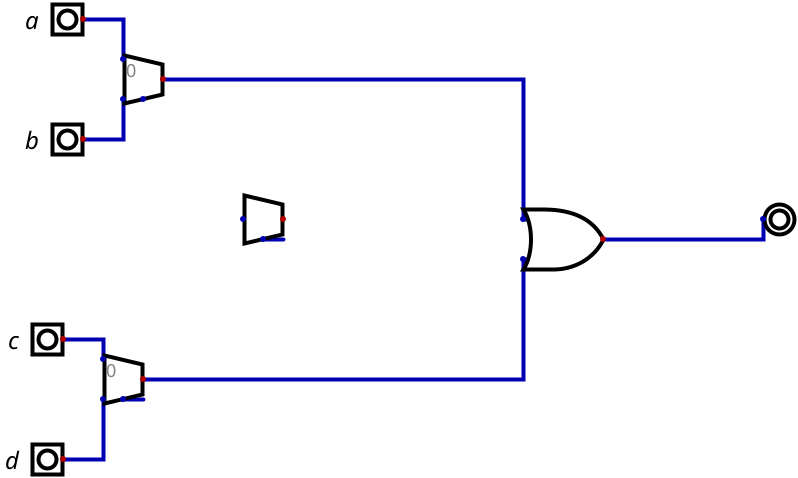
Or(a=sel[0], b=sel[1], out=outor);
Not(in=outor, out=out00);
/**
Algo to determine sel[2] = 11
IFF sel[0]=1 and sel[1]=1 return 1, that is true. See Truth table above.
**/
And(a=sel[0], b=sel[1], out=out11);
/*
Algo to determine sel[2]=10
IFF sel[0]=1 and sel[1]=0 return 1
Truth table:
a b Notb And(a, notb)
0 0 1 0
0 1 0 0
1 0 1 1
1 1 0 0
nb: when program loads it sets sel[2]=00. Therefore notsel1=1. Hence when changing sel[2] to 10, notsel1(1) =0.
*/
Not(in=sel[1], out=notsel1);
And(a=sel[0], b=sel[1], out=out10);
}
I have a problem with the Not(in=sel[1], out=notsel1).
When I load the chip in HardwareSimulator the sel[2]=00 by default, which sets notsel1 to 1. So when I change the sel[2] to 10 and run the program again it gives me notsel1=0. Which does not give me the result i expected that is '1' for And(sel[0], b=notsel[1], out=out10);
Can you please advise how I can overcome this issue?
Thanks in advance
John