Problems with logisim

classic Classic list List threaded Threaded
2 messages Options
Reply | Threaded
Open this post in threaded view
|

Problems with logisim

tyler1313
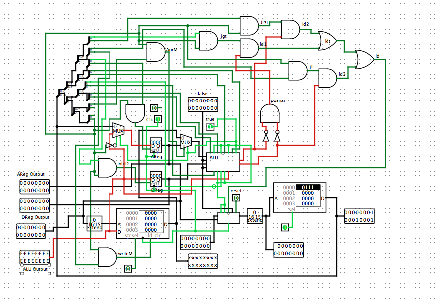
So i built the hack computer in logisim according to http://people.duke.edu/~nts9/logicgates/CPU.hdl however when I try to test it out it doesn't work as it is supposed to. For instance when the output of the ROM is 0vvv vvvv vvvv vvvv it is supposed to store a 15 bit value in the A register however that does not happen, the A register just stays at 0000 0000 0000 0000. I also have some red wires and I'm not sure why. I'm fairly certain I built it exactly as it is built in the Hack simulator. Any help is appreciated!
Reply | Threaded
Open this post in threaded view
|

Re: Problems with logisim

cadet1620
Administrator
The red wires are errors caused by conflicts or values that can not be determined at reset. Errors can propagate through logic gates, so you need to trace backwards to see where they are originating.

In this case, it looks like the error is inside your ALU and being propagated out the 'out', 'zr' and 'neg' signals. Why does your ALU have so many pins?  it should just have x, y, zn, nx, zy, ny, f and no inputs and out, zr and ng outputs. (Right click on ALU and pick 'View ALU' to see what is happening in there.)

"The A register is not loading..." Are you toggling your clock input? I would expect it load with EEEE because of the error input value.

You are getting that error input from the Mux because its 'sel' is tied to 1, not to an appropriate control signal.

Suggestions:
Don't run wires from an input to all the chips that need the clock. Use the Wiring:Clock part and connect one of them to each place the clock is needed. This will unclutter your diagram and you can toggle the clock using Control+T on the keyboard and they will all change. You can also have logisim continuously change the clock automatically at various speeds. See the Simulate menu.

Don't use inputs for constant 0 and 1; use Wiring:Constant and put then every where the constant needs to be used.  Don't run extra wires all over.

Learn about Wiring:Tunnel. This lets you make connections between parts without wiring clutter. They are very useful for things like instruction[15] which gets used all over the same place. Tunnels with the same name are connected together.

You can replace your tree of 2-way splitters with a single 16-to-splitter. Change both 'fan out' and 'bit width in' to 16. Right click on the splitter and pick 'Distribute descdending' if you want the individual bus wires in the other order.

I like the Narrow 'gate size' better for the simple gates.

--Mark