Question about feedback from DFF output to Mux in a 1-bit register

classic Classic list List threaded Threaded
6 messages Options
Reply | Threaded
Open this post in threaded view
|

Question about feedback from DFF output to Mux in a 1-bit register

Yutao228
Hi,

I am studying the sequential logic part of Nand2Tetris, especially the construction of a 1-bit register using a DFF and a Mux.

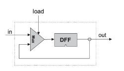
My current understanding is that the DFF stores the previous value, and its output is fed back into one input of the Mux. The other input of the Mux is the external in value, and the load signal selects whether the register should keep the old value or load the new value.

What confuses me is the timing of the feedback path. If the DFF output represents the old value from the previous time step, and this value is connected back to the Mux input, what happens when the external in is not being loaded? Does the Mux still work correctly even though the external in is not relevant at that moment?

In other words, when load = 0, is it correct to think that the Mux simply ignores the external in input and selects the old DFF output, which is then fed back into the DFF so the register keeps its previous value?

I am not asking for a full project solution. I just want to understand the timing and feedback behavior conceptually.


Thanks.
Reply | Threaded
Open this post in threaded view
|

Re: Question about feedback from DFF output to Mux in a 1-bit register

WBahn
Administrator
This post was updated on .
The Mux does what it always does. The output is equal to whichever input is selected by the 'sel' input. The input that is not selected is still there, it just has no influence on the Mux output at that time. The fact that one of the inputs is being fed back from the output of a DFF is irrelevant as far as the Mux is concerned -- it has no knowledge or awareness of where the signals driving it come from.

Reply | Threaded
Open this post in threaded view
|

Re: Question about feedback from DFF output to Mux in a 1-bit register

Yutao228
Thanks for your explanation.
Reply | Threaded
Open this post in threaded view
|

Re: Question about feedback from DFF output to Mux in a 1-bit register

Yutao228
In reply to this post by WBahn
Thank you for your explanation. That helps me understand that the Mux simply selects one input according to `sel`, and that the unselected input has no effect on the Mux output.

I have one follow-up question about the timing of the DFF output and the feedback path.

For a 1-bit Register, the intended behavior is:

```text
if load(t):
    out(t+1) = in(t)
else:
    out(t+1) = out(t)
```

My current understanding is that, during cycle `t`, the DFF first outputs the current stored value `out(t)`. In other words, at the beginning of cycle `t`, `out(t)` is already available and stable at the DFF output.

This `out(t)` is then connected to two places at the same time:

1. the external `out` pin of the Register;
2. one input of the Mux through the feedback path.

Then, during the same cycle `t`, the Mux receives both `out(t)` from the DFF feedback path and `in(t)` from the external input. After `out(t)`, `in(t)`, and `load(t)` are available, the Mux performs its combinational selection according to `load(t)`.

So the timing I have in mind is:

```text
beginning of cycle t:
    DFF output is already stable as out(t)

during cycle t:
    Mux receives out(t) and in(t)
    Mux selects one of them according to load(t)
    Mux output becomes the value prepared for the DFF input

next clock edge:
    DFF stores the Mux output
    DFF output becomes out(t+1)
```

So, in this interpretation, `out(t)` is the current state that appears at the DFF output at the beginning of cycle `t`, while the Mux output is only the next-state candidate that will be stored at the next clock edge.

There is no conflict even though the same DFF output wire is connected both to the Register’s external `out` and to the feedback input of the Mux. The external `out` shows the current state, while the feedback path allows the Mux to choose between keeping this current state or loading the new external input.

Is this the correct way to think about the timing behavior in the Nand2Tetris model?

Thanks.
Reply | Threaded
Open this post in threaded view
|

Re: Question about feedback from DFF output to Mux in a 1-bit register

WBahn
Administrator
I just read your description very quickly, but it seems correct.

The detailed timing behavior depends on exactly how the DFF is implemented, but most DFFs today are what are known as positive-edge triggered.

On the rising edge of the clock, the input is sampled and that output is then captured and appears at the DFF output a very short time later.

This has the potential to cause problems if the output is inverted and fed back into the input (and this is a very common configuration and is knows as a divide-by-two clock divider).

The DFF is actually sensitive to the input not just exactly at the rising clock edge, but to the state of that input from a small amount of time before the edge (known as the setup time) to a small amount of time after the edge (known as the hold time). The designer has to ensure that the signal at the input is a stable logic value during the setup/hold time window. If not, the output of the DFF is indeterminate.

If the propagation delay from the clock edge to the DFF output and back to the input is too small, it can violate the hold time requirement. Discrete DFF chips are designed so that the propagation delay is long enough so that this can't happen, but DFF cells used in IC designs often are not (because we want them to be as fast as possible, so we accept the responsibility of making sure setup/hold requirements are satisfied).

I killed an IC I was designing because of this. I was porting an earlier design I had done to a new process node to make the chip physically smaller and was under very tight time constraints to get it submitted for fabrication. We told the customer that we would not be able to do the verification simulations before submission and that there was a risk that there might be an issue that snuck through, but that the risk should be pretty small. They needed to show physical chips to their customer before one of their project milestones and it was actually more important that they have them, then that they work properly (since the prior chip had demonstrated that), so they told us to proceed. Well, it bit us because the new process was sufficiently faster that my new DFFs violated hold time and the chip was completely chaotic in its behavior.
Reply | Threaded
Open this post in threaded view
|

Re: Question about feedback from DFF output to Mux in a 1-bit register

Yutao228
Thank you very much for the explanation.

That clears up my confusion. I now understand that, in the Nand2Tetris model, `out(t)` is already available during cycle `t`, and the Mux uses it together with `in(t)` and `load(t)` to prepare the value that will be stored at the next clock edge.

Your additional explanation about setup time, hold time, propagation delay, and the possible hold-time violation in real hardware was also very helpful. I had not considered that level of timing detail before.

Thanks again for your time.