Some Logisim circuits to use with keyboard and screen

classic Classic list List threaded Threaded
6 messages Options
Reply | Threaded
Open this post in threaded view
|

Some Logisim circuits to use with keyboard and screen

LegenDUST
As you may know, Keyboard and Screen in Nand2Tetirs is quite... Too simple, so to say.
I tried to implement hack pc in logisim, but those IO device was trouble to me.

There is logisimn2t project, which can solve screen problem in logisim classic.

There is RGB Screen component in logisim evolution, which can act like screen, but manipulating it requires you to change it one pixel at a time, opposed to nand2tetris screen which manipulates 16 pixels at a time.

Introducing

Usage of n2tLogisimIO

n2tLogisimIO

Two circuits inside the repository, one of it is for classic and contains only one component, and the other is for logisim-evolution and contains two main components and two sub-component and one 'Usage'.

'Keyboard Delay' is circuit which gives 'delay' for built-in logisim keyboard component - it is my approach to deal with 'keyboard input data remains only for one clock cycle and disappears' problem.

'Graphic Card' is circuit which translates 'Edit screen accordingly' message, i.e. 16-bit data and 13-bit address, to two set of 8-bit x- and y-address, with two enable signal and color data.

Well I used queue (basically RAM with three counter) for minimize make sure every change is committed to screen, but limit of RGB Video component is one pixel per one clock cycle, so you may experience delay and eventual non-committed change when you manipulate screen too often (like, once per 10 instructions or so).

Anyway, I hope this can help someone.
Reply | Threaded
Open this post in threaded view
|

Re: Some Logisim circuits to use with keyboard and screen

Renslay
This post was updated on .
I once re-created the entire Hack machine in Logisim, however, I found it too slow.

My main idea was to create a screen-driver: a piece of hardware that stopped the CPU whenever there was a write instruction to the screen memory, and used 16 additional clocks to draw the individual pixels (reading bit-by-bit of the register and setting the 16 pixels). Once it was done, it gave back the control to the CPU.

I could run a JACK application on this virtual machine; but it was super slow; it took many seconds just to draw a single line of the screen. So I recreated the whole thing in Digital. This was much, much better, Pong was quite playable, though not perfect.

SPOILER ALERT - HACK MACHINE IMPLEMENTATION!

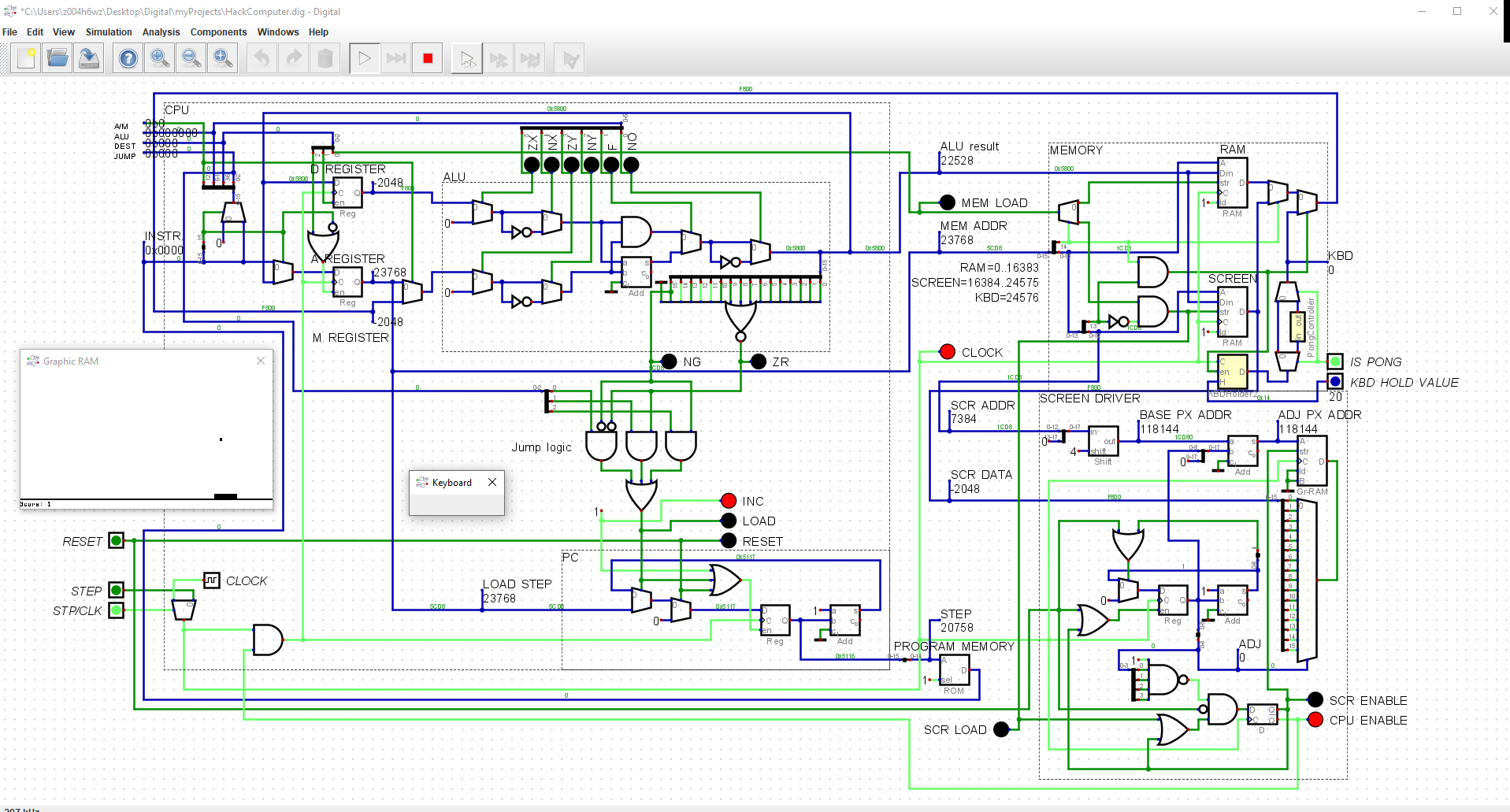
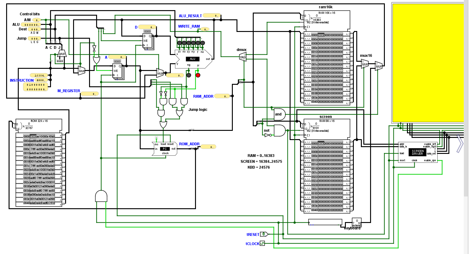
Below is the screenshot I made.

The RAM (top right corner) has 3 components: RAM, SCREEN, KBD (keyboard). Whenever SCREEN is updated, the Screen driver (bottom right) kicks in.

The bottom right part is the Screen driver. The raw screen address is transformed into the GR-RAM address (the chip I used for graphic display). The transformation steps are SCR ADDR (the raw address), BASE PX ADDR (what the graphic chip needs), and ADJ PX ADDR (step-by-step incrementation to read the bits and address the individual pixels).

Below that (the middle part of the Screen driver), there is a similar mechanism to the program counter: it counts from 0 to 15. It increases the pixel address, so we can see the next bit of the register.

At the bottom part there is a flip-flop mechanism which turns off the CPU clock while the screen is refreshing (it's either CPU or SCR, showing whenever the clock is driving the one or the other). While the screen refreshes, the CPU stops, and when the Screen PC reaches 16 and wraps around to 0, it swaps back to the CPU.

For the keyboard I had to design a separate chip to make it work, because it was not entirely HACK-compatible... That's a different story that worth at last an entire page. :/

Reply | Threaded
Open this post in threaded view
|

Re: Some Logisim circuits to use with keyboard and screen

LegenDUST
Yup, logisim is really slow, but that was what I had (and only thing I knew) when I decided to make it again without HDL...

Anyway I had fun making this.
Reply | Threaded
Open this post in threaded view
|

Re: Some Logisim circuits to use with keyboard and screen

Renslay
This post was updated on .
I found my Logisim implementation of the screen driver. See attached image.

When RESET is on and there is a clock signal, it clears the screen.

ADDRESS13 is a 13 bit screen address; basically the register that belongs to the screen in RAM according to the HACK design (already shifted, so ADDR=0 means the first register belongs to the screen). This address is transformed into X and Y coordinates to the screen itself (see the X0, X and Y labels). The X coordinate is then incremented by 1 with every clock signal.

IN16 is the content of the register at ADDRESS: these are the 16 pixels we want to display.

A counter logic (X_SHIFT) is there to step through the bits of IN16 and set the pixels accordingly (A 16 bit MUX is used here).

LOAD: we only set the pixels if this is on.

CPU_CLOCK_ENABLE: this goes back to the HACK CPU; while the screen driver is working, every clock signal goes here, and the CPU waits. When we iterated through all 16 pixels, this turns on, so the clock drives the CPU normally again.

On the top right part there is an additional logic to decide whenever we write to the left or the right screen; since Logisim only allow as 256*256 screens.
Reply | Threaded
Open this post in threaded view
|

Re: Some Logisim circuits to use with keyboard and screen

Renslay
In reply to this post by LegenDUST
Here is the same, but as a separate chip.
Reply | Threaded
Open this post in threaded view
|

Re: Some Logisim circuits to use with keyboard and screen

Renslay
In reply to this post by LegenDUST
And here is the complete HACK machine with the screen driver and keyboard (the right side of the screen is not visible, but is wired like the left side).