|
|
|
|
Not sure what to do. Not asking for tips, just moaning. Half the battle is confidence really, since I'm not even trying, it's like I've decided "this is where I will fail" for whatever reason I have decided that.
|
|
|
Hi,
I skipped that too. The leap was too big. And I have to make to many assumptions. For conditional jumps you need status signals, where do they come from ? I do have an idea of how to implement one but there's too much guess work.
Have a nice Sunday,
Stephan
|
|
|
Yes, the CPU is the hardest hardware project from the book. The good news is, that it consists of relatively simple parts. You can start by implementing the instruction decoder, because it drives a lot of the internal signals.
And you can leave the jump logic for last, because it's a bit confusing, but on the other hand it only changes the PC.
|
|
Administrator
|
My suggestion for writing the CPU is to start by printing several copies of the CPU diagram so that you can write notes and draw on them.
I just created a PDF that prints the diagram to fill 8.5x11 / A4 paper. You can get it from this post: Printable CPU Architecture drawing.
Label all the parts' (c) inputs and outputs. Make sure you account for all the parts' I/Os. For the moment, don't worry about determining which Mux inputs are a/b. ("decode" is not a part; it represents the logic you will add in CPU.hdl)
You can start by writing the HDL for all the parts shown in the diagram.
Give the wires/buses names related to the part. For example:
ALU(x=aluX, y=aluY, zx=aluZx, ..., out=aluOut, zr=aluZr, ng=aluNg);
You will end up changing some of these names as you analyze the interconnections between the parts and determine the logic/connections for the control signals.
Some things might be immediately obvious from the CPU diagram. For instance, aluX is directly connected to dregOut. You can immediately use dregOut in the ALU's x input. (In most cases I like using the name of the part that generates the wire, hence dregOut. Control signals generated bu "decode" use the controlled part's name. Do what makes the most sense to you.)
Draw the data flow for various instructions like @1234, A=D, M=D, etc. Here's D;JEQ
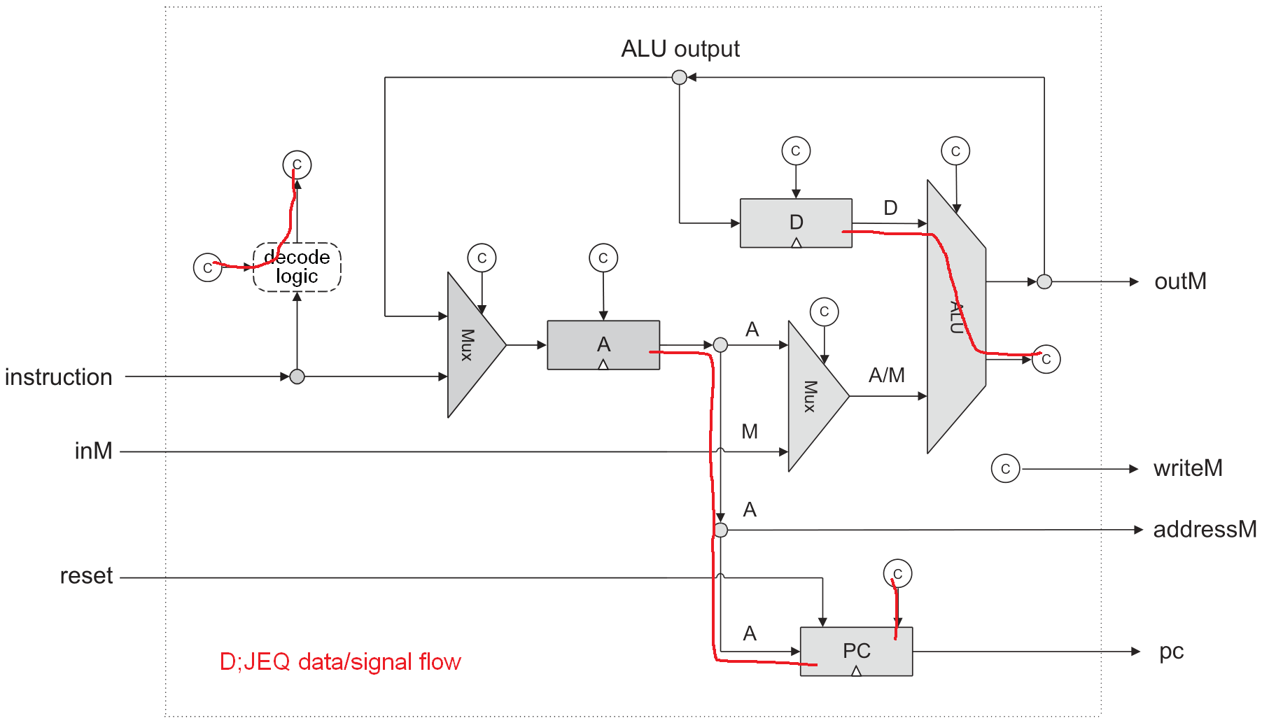 You will see that there are some control signals that are only active during a-instructions and others that are only active during c-instructions. It is useful to create two control signals 'aInst' and 'cInst'.
Useful hardware trick: A Mux can be an And gate. If you tie 'a=false' then out = b & sel. You can do this with a Mux16 and get out[*] = b[*] & sel.
--Mark
|
|
|
Thank you for these awesome tips. I shall give this chapter 5 another go.
Also, love the Mux could be an AND, brilliant sir!
|
|
Administrator
|
A two-input Mux is actually universal in that ANY logic can be implemented with nothing but a big pile of such Muxes. The same is true for Nand gates and Nor gates, which is what most people know about. But it is also true of four other two-input gates.
|
|
|
Thanks.
Also, good tips on starting with the decode section. I think starting with Mark's idea of copying the CPU worksheet and highlighting the different paths of the various register loading, etc will be good. I can then start with the decode section and worry about the jumps later. This may work for me. Appreciate the helps!
|
|
Administrator
|
You can also break things down into smaller chunks. For instance, you might start out by only working with operations that only write to the D register (i.e., don't read from any registers, so instructions like D=0, D=1, and D=-1). Then add instructions that also read from the D register (like D=D+1). At that point, you could either expand by including instructions that read from the A register, or by including instructions that write to the A register.
At each step, add a set of instructions that all have one thing in common so that you can just focus on that one thing. Be sure to test that your added instructions work correctly AND that you didn't do anything to break the instructions that had already been added.
|
|
|
Good idea!
I would assume that I would need to hdl code the CPU, RAM, ROM, KBD and SCREEN all together and then I can start a piece at a time like you are saying.
Thanks for tips!
|
|
Administrator
|
linuxford wrote
Good idea!
I would assume that I would need to hdl code the CPU, RAM, ROM, KBD and SCREEN all together and then I can start a piece at a time like you are saying.
Thanks for tips!
Yep. That part is often referred to as the data path of the processor. Then what you are left with is the control path.
|
|
|
Thank you again for the great tips.
It's taking some time and I'm really having to read and reread to make sure I understand the material, but the CPU is coming along. I have the basic control logic working correctly (good suggestion again) and will be working on the jump logic.
Great tips to take it a piece at a time, this really make it manageable. And also to print out the CPU from the book, and highlight the flows as was also suggested.
Also one needs to understand the machine language (the usage of the registers and the A and C instructions). Until I understood this, I was not able to code the CPU. So I would highly recommend for those struggling like I did, to go back to chapter 4 . You have to really understand chapter 4 and play around with doing different assembly programs. It gave me insight into how the machine should operate.
Then in Chapter 5, I had a good feel of how the assembly commands related to the registers and different A and C instructions. Of course, I had quite a few different bugs to work through as it can be a little tricky.
One other tip that one could consider is to take the CPU as it is in the book, and hardcode the control bits to either high or low initially. Then load the hdl code in the Hardware simulator without errors. From there (per the suggestion, thank you again), take a look at the compare script to see what it is testing. Then add logic to get past the first hurdle without error. Once that occurs, then add more logic to get past the second test. Etc.. After I did this, I was able to find bugs more quickly, and things started going smoother.
|
|
Administrator
|
This post was updated on .
linuxford wrote
One other tip that one could consider is to take the CPU as it is in the book, and hardcode the control bits to either high or low initially. Then load the hdl code in the Hardware simulator without errors. From there (per the suggestion, thank you again), take a look at the compare script to see what it is testing. Then add logic to get past the first hurdle without error. Once that occurs, then add more logic to get past the second test. Etc.. After I did this, I was able to find bugs more quickly, and things started going smoother.
This is essentially the approach often taken by Agile software development, which is summarized by the manta, "We shall write no code until we have a failing test". Then you develop your code in order to pass the tests one by one. If the tests are well thought out and sufficiently encompass the behavior spectrum, when you pass all the tests, you are done.
But there is a potential problem when applying this approach to N2T because you then have to pass the tests in the order the authors wrote them. If they happen to choose to put the most comprehensive tests first, followed by detailed tests later on, then you might have to get almost the entire implementation done before you can pass even the first one. The good news is that human nature leads people to write small, simple tests first and leave the more-comprehensive stuff to the end to cover things that they can think of that didn't get covered by the simple stuff. Plus, I would expect that the authors want the test suites to help guide the development process as much as possible, so they likely ordered the tests with that in mind.
|
|
|
Great feedback and insights, thank you for sharing!
|
|
|
Hello,
First, just wanted to high-five now that I've passed all the CPU tests after adding the final touches of the jump logic. It was pretty exciting! Thank you so much for all your input and tips, etc! I will add the memory and keyboard and screen which should not be too bad, the CPU was the huge hurdle.
Details: I had tried a decade ago with the first edition but couldn't get the CPU built. I recently purchased edition 2, and following the Coursera lectures. The updated information filled in some gaps I think for me to where I was understanding it. I then got to the CPU and was stuck and overwhelmed. This thread gave me the encouragement and also needed insights and approach to take. So again, many thanks!!!
I amazed at the simplicity and elegance of the hardware!
Another take away was the necessity and the power of abstraction in learning and design.
Thank you and thank you to the team! This is an incredible book and staff!
I am fascinated by the Hardware, but after exploring the hardware more in the wild, I plan on coming back for Part 2 and software.
|
|
|
i did something similar. i quit for 3 years after hitting the CPU section. then when i came back through blood and sweat and tears managed to get it completed. it's a great feeling. thanks for enjoying my thread
|
|
|
 Onward to software!!
|
|

