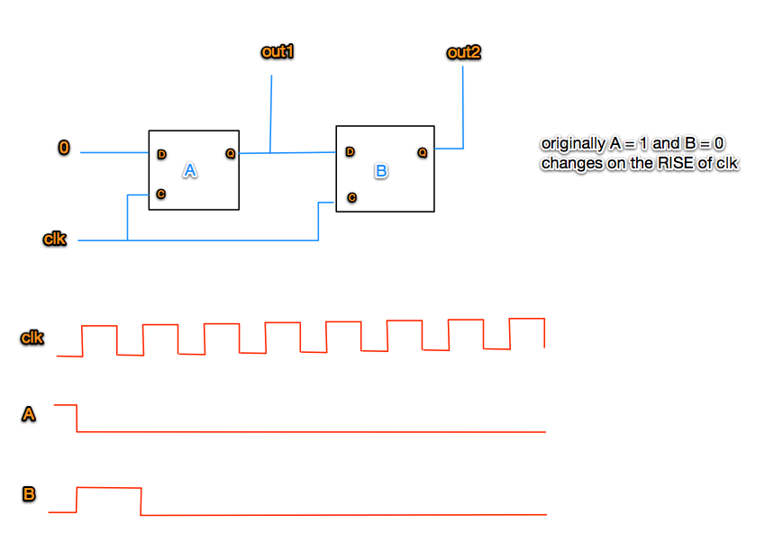
The easiest real hardware implementation of DFF is what's called a Master-Slave DFF. Think about it as consisting of two DFF's in a row. The first one latches D on
falling edge and the second one latches on rising edge.
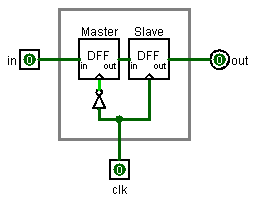
The internal master doesn't care about what's happening on the rising edge of the clock because it saved the value on the falling edge. On the rising edge, the data that was saved on the falling edge is transferred to the slave DFF and appears on the output.
One must be careful using master-slave flipflops in real word designs because of the dead time between falling and rising edges where they don't sense their input.
There are also true edge-triggered flip-flops. They work in series because real world parts always have a propagation delay from clock input edge to data output change. One of the hardware engineer's tasks is to ensure the all of the timing requirements are met for the parts he uses.
--Mark