|
|
|
|
I don't understand the logic behind ALU "feedback" in A and D registers. why do we need it?
|
|
|
I'm not sure what you mean by "feedback" here. If you mean why we connect the ALU output to the A or D registers, then the answer is, that we need to do that in order to implement assembly instructions like A=A+D or D=D+1.
|
|
|
yes I mean just that. can you explain how we are doing A=A+D or D=D+1 ?
my logic is: at time t=0, C instruction arrives. Since this is a C instruction, the mux selects the previous ALU output which can be anything. And since load bit of the C instruction is 1, the A register is loaded with the previous ALU value. This value may not be the same as what we want from our C instruction (in this case, A+D). this is where I am confused.
|
|
|
The registers are implemented using data flip-flops (DFFs), so you need to understand how that works.
The DFF, as implemented in this course, can remember a single bit for a single time-cycle. What does this mean? First of all, time is measured by the clock signal. You can think of it as a wire, which connects to all DFFs in the computer and which changes from 0 to 1 to 0 to 1 to 0 to 1 and so forth at regular rate. In the simulator, this wire is not explicitly shown, it's just that every DFF you create is connected to it. And you progress the time by pressing the tick/tock button. Basically, tick means that the clock goes from 0 to 1, and tock means that it goes from 1 to 0.
Now the DFF remembers its input when the clock goes from 1 to 0. This means that whatever happens to its input at any other time, the output will not be affected. This is how the cycle is "broken" and the register can both be an input to the ALU and the place to store the value of the ALU computation.
Please note, that I don't remember the exact details from the book. You'll have to check if the tick and tock are actually these transitions or the reversed ones and if the DFF is remembering its input when the clock goes from 1 to 0 or from 0 to 1. These are all details of the implementation, but the principle is the same in both cases.
|
|
|
sorry if I missed your point but I do know these details. But I still don't understand how A=A+D or D=D+M etc. commands are running in this CPU implementation.
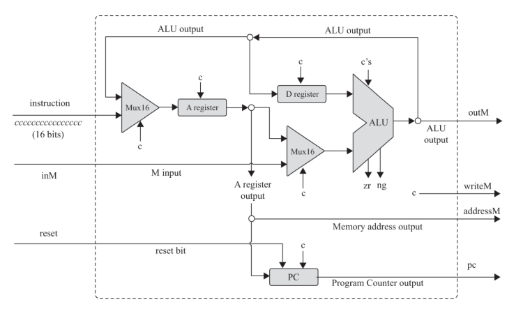
here is the implementation of the CPU if you need it:
|
|
|
This is not the full implementation. What is missing here is the various control signals, which are denoted by the letters c. This is not 1 signal. What you need to do is to figure out how to compute them to implement the Hack CPU semantics.
WARNING: Minor spoiler! I'll "implement" part of the CPU below, to give you an idea how to proceed, hopefully without helping too much :)
For example, let's say we are focusing on the A register. There are two control signals that we need to trigger: 1. the A register's load signal (I'll call it c1), 2. the control signal for the Mux16 that stands before it - c2.
From the CPU specs we know that A register should be loaded in two cases: either if the instruction is an A-instruction, or if the A register is a target in a C instruction. We can determine if the instruction is A or C by looking at bit 15 of the instruction input, where 0 means A and 1 means C. And we can determine if A register is a destination, by looking at bit 5 of the instruction word.
So, the c2 control bit can be just the inverse of bit 15 of the instruction word. (Or it could be the bit 15 itself, just reverse the Mux's inputs.)
The c1 is a bit more complex: it connects to the load input of the register, which should be 1 when (bit_15 == 0) OR (bit_15 == 1 AND bit_5==1). These are just an AND and an OR gate connected to appropriately.
For the next part, I'd go with the D register, then the second MUX16; then the ALU. The most complex part is the PC control, which should handle the jumps. I'd leave that for last.
I hope this will help you.
|
|

