Hezi wrote
What do you mean by "no provision for arithmetic shifts"? AFAIK a left shift is a multiplication by 2 and a right shift is an integer division by 2. But that should be true for my design. Is there anything else?
So let's say that the number in the register is -2. What will the value be after you right shift it one place? Is it -1 or is it 127?
Therein lies the distinction between a logical right shift and an arithmetic right shift.
Your suggestion for implementing an HDL is changing the design. I know how to implement *a* bi-directional shift/rotate Byte register in HDL, but I couldn't find an easy way to implement *this* design in HDL.
Depends on what you consider a changed design. I think I could write an HDL file that if one circuit were built from your diagram and another from the HDL file, the two circuits would be identical. Only the conceptual organization would be different.
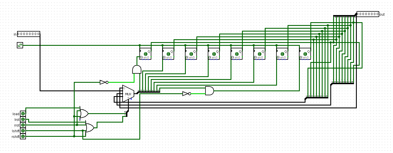
I did not follow the general line of the course - to use as little chip parts *in an HDL implementation* as possible. I know I could encapsulate the MUX logic in a separate design and only have inputs, output and 8 bit chips in this design, but that would bind the number of MUXes (and possibly the number of ORs also) to the number of bits in the register. In my design, if I am not mistaken, one could increase the number of bits and still only have only one MUX and 2 ORs, limited only by the space on the board available for the width of the bus (at least theoretically). I don't know if that is a good practice for designing chips, but that is what I was going for.
That rule from the course has to be taken with a huge grain of salt. At the very least, the number of chips instantiated by the parts being called has to be taken into account. Also, starting with nothing but NAND gates means significant inefficiencies from the start. Consider the implementation of a NOR this way. It would be an OR followed by a NOT. But then the OR is built from one NAND and two NOTs and a NOT is built from a NAND, so four NAND gates. Yet in the real world a NOR is built as a fundamental gate and is the same size as a NAND (each has four transistors in classic CMOS) and an OR is built using a NOR followed by a NOT (that uses just two transistors).
I think what the authors are going for is conceptual complexity but they wonder off on a tangent that really isn't justified.