Draw and Simulate your chips / logic gates

classic Classic list List threaded Threaded
6 messages Options
Reply | Threaded
Open this post in threaded view
|

Draw and Simulate your chips / logic gates

ashort
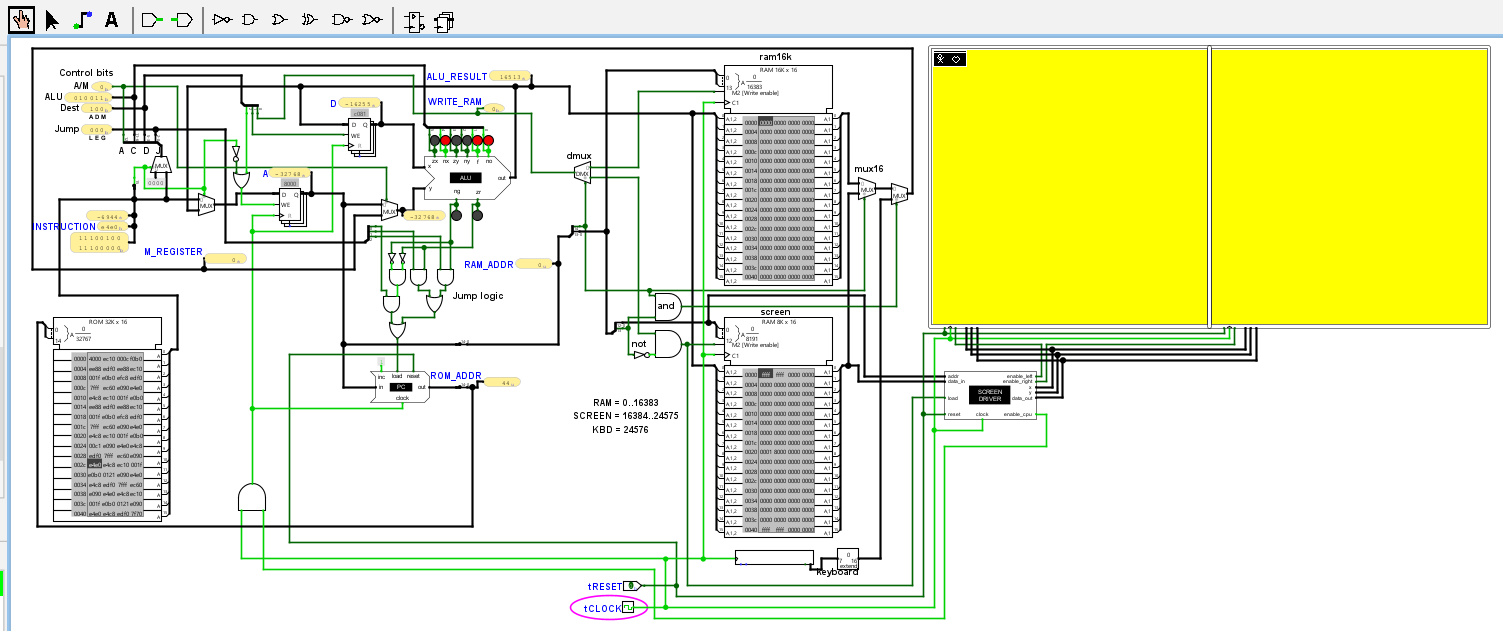
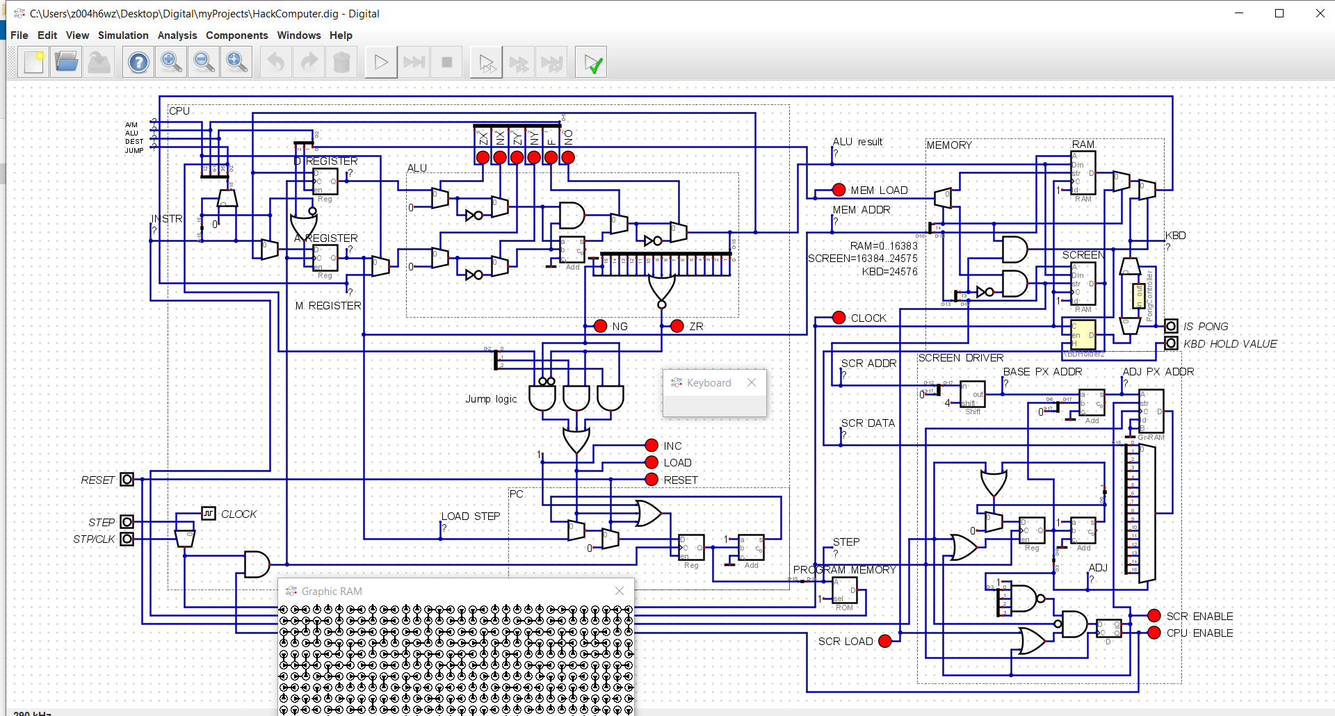
After completing the course, I thought it would be fun to go back and draw and simulate all the logic gates and chips visually, since the supplied Hardware Simulator does not do this.  By “visually”, I mean you see switches for the inputs, and light bulbs for the outputs, and the connections between pins are color-coded to show low or high signals, and you can create your own custom chips made of sub components.  

I decided to use the third party program Logicly, because the user interface is really easy and beautifully designed.

I was able to construct the entire Hack chip set, and simulate running a program.  Here are some interesting things I ran into:

(1) Instead of RAM16k, I only went up to RAM8. So the RAM memory is 8 16-bit registers.  This is because in trying to construct RAM64, I noticed the file load time was getting too long, and I realized that for simulation purposes, 8 registers is all I needed.

(2) Instead of ROM32k, I built a simple ROM chip with only 8 16-bit instructions (for the same file performance reasons above). The 8 fixed instructions I put in are:

0 0000000000000010 @2 // A = 2
1 1110110000010000 D=A // D = 2
2 0000000000000000 @0 // A = 0
3 1110011111001000 M=D+1 // RAM[0] = 2 + 1 = 3
4 1111000010010000 D=D+M // D = 2 + RAM[0] = 2 + 3 = 5
5 1110001100001000 M=D // RAM[0] = 5
6 0000000000000110 @6 // A = 6
7 1110101010000111 0;JMP // goto 6

(3) I completely ignored Screen and Keyboard

(4) The DFF chip is built-in for nand2tetris, but I decided to build it myself in Logicly.  And this is where I learned a huge lesson. What happened is I constructed DFF myself using NAND gates feeding into themselves, using a classic configuration.  But later when I built and simulated the Program Counter chip (PC), I noticed the light bulbs were going haywire.  While the clock input was high, the PC was incrementnig wildly.   This is when I realized the DFF that I built was LEVEL triggered, not EDGE triggered.  Positive EDGE triggered means the output can only change at the moment when the input changes from low to high.  LEVEL triggered means the output can change as long as the level is high, even during the short pulse from the clock.   I fixed my DFF to be positive edge triggered, and things predictably worked as it should, perfectly synchronized, ticks and tocks.

(5) I used only 1 oscillating clock input for the entire computer (in the top-most Computer). This means chips like Bit and Register have a CLK input switch which feed off of the top-most oscillating clock.  Note that in the nand2tetris HDL files, it is sort of implied that there is only ONE clock driving all the sequential chips.  

(6) The Logicly program does not allow for grouping multiple pins together, e.g. I had to painstakingly drag 16 pins for a 16-bit connection, whereas in many cases it would be easier to group them and treat them like one pin.  Alas, Logicly does not support this (at least not in version 1.11.4)

In the end, it was very satisfying to watch my CPU literally light up as it processed an instruction, and to see how all the fetching of instructions is driven and synchronized by the oscillating clock.    Using the simple Hack program above, I could see visually all the instructions and values pumping through the system, one by one, automatically!  It makes your chips comes alive.  Well worth doing this, either after the course like I did, or perhaps while your are working on and debugging your chips.

You will definitely gain a better understanding of the difference between combinational and sequential chips, and of how the clock signal works with positive edge triggering, and how that drives the process.   Highly recommended!
Reply | Threaded
Open this post in threaded view
|

Re: Draw and Simulate your chips / logic gates

WBahn
Administrator
Very impressive -- and educational for you.

You actually lucked out with your DFF. Apparently Logicly does something in its gate simulation that imposes some kind of nonzero gate delay on the logic parts -- some simulators due and some don't. Without that delay you would still have problems because you would almost certainly violate the setup and hold time requirements for your DFF.

I actually killed a chip design by not taking this into account. We were porting a design to a smaller process, which meant it was faster. We were under a serious time crunch and so didn't do the normal low level simulations since we knew we has a good design. But the end result was that the logic went haywire and it didn't take long after our customer complained to figure out why. Fortunately, our customer was good about it since we had warned them that to meet their schedule we would not be able to fully verify the new chip; they didn't even bring up the fact that we had characterized the risk as "low".
Reply | Threaded
Open this post in threaded view
|

Re: Draw and Simulate your chips / logic gates

wafalou
In reply to this post by ashort
Dear

What is the simulator you use?

How I can found the design?

Regards
Reply | Threaded
Open this post in threaded view
|

Re: Draw and Simulate your chips / logic gates

ashort
I used Logicly, as I wrote in my post :-)
Reply | Threaded
Open this post in threaded view
|

Re: Draw and Simulate your chips / logic gates

ashort
And it seems I could have used negative edge triggering. My post seems to suggest positive edge triggering. But either edge should work
Reply | Threaded
Open this post in threaded view
|

Re: Draw and Simulate your chips / logic gates

AndyPro720
Sounds worth a shot, mind sharing the file?
Edit:
I do recall seeing Cadet and a few others recrate the same on logicism a while ago, although there the functionality is a bit limited