Hardware simulator - implementation artifact?

classic Classic list List threaded Threaded
4 messages Options
Reply | Threaded
Open this post in threaded view
|

Hardware simulator - implementation artifact?

Foggerty
Hi, i've just finished the PC - implementing it was fun! - and have a question re the hardware simulator.
Because I wanted 'sel' to be set by either of the 1-bit inputs, I just did:

Thing(a=in, out=out, sel=load, sel=inc, sel=reset);

This doesn't work, but in the real world I'd expect it to; the three wires would fan-in to the single sel input, and so long as one of them was '1', everything would be fine. Right?

The below does work, but look! I wasted 5 input bits, which the programmer in me cannot stand :-( (There's only a 8-way builtin OR gate.)

Or8Way(in[0]=load, in[1]=inc, in[2]=reset, out=OrOut);
Thing(a=in, out=out, sel=OrOut);


Am I correct in guessing that the hardware simulator, if it runs into the former situation, will just check each in turn (load, inc, reset), and if only the first if set to '1', it will override the 'sel' input with the following '0's? Or am I missing something?

Cheers,

Matt.
Reply | Threaded
Open this post in threaded view
|

Re: Hardware simulator - implementation artifact?

cadet1620
Administrator
Foggerty wrote
Hi, i've just finished the PC - implementing it was fun! - and have a question re the hardware simulator.
Because I wanted 'sel' to be set by either of the 1-bit inputs, I just did:

Thing(a=in, out=out, sel=load, sel=inc, sel=reset);

This doesn't work, but in the real world I'd expect it to; the three wires would fan-in to the single sel input, and so long as one of them was '1', everything would be fine. Right?
Normally what happens when you directly wire the outputs of two CMOS gates together is that the magic smoke comes out and the parts stop working.

  CMOS And gate

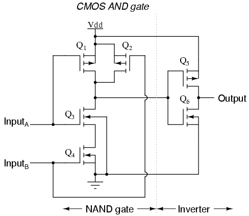
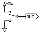
When the output of the And gate is True, transistor Q5 (pull-up) is turned on and Q6 (pull-down) is turned off. When the output is False, Q5 is off and Q6 is on. Effectively, the output connected directly to power supply or ground. Think of the output as a two-way switch

  SPDT Switch

When two competing outputs are connected together, power is connected to ground through the pull-up of one of the outputs and the pull-down of the other output, resulting in a short circuit. One, often both, of the transistors will burn.

Also, in the real world you don't want to leave unused inputs floating. They can pick up noise, causing output glitches, or they can cause the gate to enter analog operation which can also result in burnout.

(I'd have written the simulator to error on unconnected inputs, so you'd need to write
  Or8Way(in[0]=load, in[1]=inc, in[2]=reset, in[3..7]=false, out=OrOut);
to ensure that all the inputs are connected.)

--Mark

Reply | Threaded
Open this post in threaded view
|

Re: Hardware simulator - implementation artifact?

Foggerty
Ahhh, gotcha - so I think my mistake was thinking of each gate as a discrete 'chip' connected by wires (my imagination gets rather fuzzy around this point), but yes, they're all supposed to be a part of the same CMOS. I think I need to do some reading on the actual physical implementation, as it's something I know very little about. Thanks!
...the magic smoke comes out and the parts stop working.
I'm totally going to steal that line :-D
Reply | Threaded
Open this post in threaded view
|

Re: Hardware simulator - implementation artifact?

cadet1620
Administrator
The same problem occurs when you connect the outputs from two discrete ICs.  Current flows out of the output pin that is driving high and into the output pin that is driving low.

It's a bit counter-intuitive that current can flow into something that's called an output.

--Mark