LFSR32Rand: Theory of operation
Preliminaries — Shift Registers
A
shift register is a register with the added capability of modifying its stored data by shifting it one bit to the left or right. Shift registers are often used to convert parallel data to serial bit streams and vice versa. Shift registers can have serial-input, serial-output, parallel-input and parallel-output in various combinations depending on their task.
The most generic shift register has both types of inputs and outputs. Here is an example shift register schematic and HDL file:
![4-bit [right] Shift Register schematic](http://nand2tetris-questions-and-answers-forum.52.s1.nabble.com/file/n4029952/lfsr-sr-pio4.gif) |
| 4-bit [right] Shift Register |
/**
 *  16-bit Shift Register (left-shifting).
 */

CHIP ShiftReg16 {
    IN  in,         // Serial input
        pIn[16],    // Parallel input
        shift,      // True to shift when clocked
        load;       // True to parallel load when clocked (overrides shift)
    OUT out,        // Serial output
        pOut[16];   // Parallel output
PARTS:
    Mux16(sel=load, out=regIn,
          a[0]=in, a[1..15]=regOut,     // regIn = (regOut<<1) | in
          b=pIn);                       // regIn = pIn
    Or(a=shift, b=load, out=regLoad);
    Register(load=regLoad, in=regIn, out=pOut, out[15]=out, out[0..14]=regOut);
}
The LFSR32Rand-theory.zip file (bottom of post) contains this HDL and a test file to exercise it.
Linear Feedback Shift Register
A
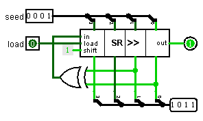
linear feedback shift register connects some of its parallel outputs back to its serial input through a network of XOR gates. Here is a schematic of a 4-bit LFSR (uses the 4-bit shift register shown above):
 |
| 4-bit Linear Feedback Shift Register |
This LFSR cycles through this sequence:
0001   1000   0100   0010   1001   1100   0110   1011
0101   1010   1101   1110   1111   0111   0011  (0001)
Notice that the value 0000 is missing from the cycle. If the LFSR contains all zeros, it will never change.
The LFSR32Rand-theory.zip file (bottom of post) contains HDL and test files for this 4-bit LFSR and a 32-bit LFSR that is the LFSR used by LFSR32Rand.
LFSR32Rand.jack
The fundamental data structure in LFSR32Rand is a 32-bit shift register comprised of the two 16-bit fields
msw and
lsw
Left shifting the double-word register requires three steps:
• msw must be shifted by doubling.
• msw bit 0 must be set to lsw bit 15.
• lsw must be shifted by doubling.
The Jack code to do this uses the < comparison to test if bit 15 is set, and takes advantage of the comparison result being -1 (true) or 0 (false).
let msw = (msw+msw) - (lsw < 0);    // '<' returns -1 if true
let lsw = lsw+lsw;
The fundamental function in LFSR32Rand is randBit() which generates the next random bit that will be used to compose the random numbers.
It computes the next input bit to the LFSR and then shifts the LFSR to the left and inserts the new bit.
Jack (and Hack) is not good at XOR, so randBit() uses the fact that XORing multiple bits together is the same as adding them modulo 2. The code is rather sneaky in that it adds true and false values as surrogates for the individual bits that need to be XORed.
let bit = ( (msw < 0)               // true if 0x80000000 set
          + ((msw & 64) = 64)       // true if 0x00400000 set
          + ((lsw & 4096) = 4096)   // true if 0x00001000 set
          + ((lsw & 32) = 32)       // true if 0x00000020 set
          ) & 1;
Example Files
Note that the schematics in this post show right-shifting circuits, but the example HDL files are left-shifting
LFSR32Rand-theory-1-0.zip contains:
| ShiftReg4.cmp | | 4-bit shift register |
| ShiftReg4.hdl |
| ShiftReg4.tst |
| ShiftReg16.cmp | | 16-bit shift register |
| ShiftReg16.hdl |
| ShiftReg16.tst |
| LFSR4.cmp | | 4-bit linear feedback shift register |
| LFSR4.hdl |
| LFSR4.tst |
| LFSR32.cmp | | 32-bit linear feedback shift register |
| LFSR32.hdl |
| LFSR32.tst |


![4-bit [right] Shift Register schematic](http://nand2tetris-questions-and-answers-forum.52.s1.nabble.com/file/n4029952/lfsr-sr-pio4.gif)


