NOT gate solution not making sense

classic Classic list List threaded Threaded
6 messages Options
Reply | Threaded
Open this post in threaded view
|

NOT gate solution not making sense

rich
I seem to be one of the few who doesn't understand why the answer for the NOT gate in the HDL works.

The schematics clearly show only one wire going into a NOT gate.

Somehow though, a Nand gate is the exact same thing as a NOT gate- all we're doing is hooking up the ins and outs of a Nand gate and pumping electricity through it. They're equivalent. Yet, Nand requires two inputs.

So, when we have a NOT gate, is it one wire going in or two? Is a NOT gate secretly built with a Nand gate inside of it where the one input is split into two to make the gate work?

Clearly, I'm missing something pretty basic.
Reply | Threaded
Open this post in threaded view
|

Re: NOT gate solution not making sense

ybakos
You're on a desert island. You have a chest full of NAND gates. To get off the island, you need to build a NOT chip. What materials do you have? NAND gates. Your goal is to figure out how you can build NOT out of the parts you have.

A Nand gate is /not/ the exact same thing as a Not gate. They behave very differently, and, as you state, they have different inputs.

A Not gate has one in and one out. How does it behave? Your last question is on the right track.
Reply | Threaded
Open this post in threaded view
|

Re: NOT gate solution not making sense

rich
Wow, pretty active boards here. Thanks for the quick response.

I have the solution. I don't understand why though.

It seems that all a NOT gate is, is a Nand gate with the A * B inputs overlapped onto one "in" wire.

What's not clear to me is how this would work in the real world. The NOT gates in the schematics, like in Figure 1.6, only have one wire going in and out of the NOT gates. That's one input from one wire. That means that inside that NOT gate, there's no way to split that input into an A * B input that the Nand gate needs to function.

So, in the real world, how does the NOT gate reverse the signal?
Reply | Threaded
Open this post in threaded view
|

Re: NOT gate solution not making sense

ybakos
Well, to be clear, a Not in the real world isn't necessarily made of Nand gates. See the reading for why we start with Nand. (Mark can probably chime in about real Not implementations.)

As for the construction, surely we can take one wire, and physically connect two to it, and connect each of those two to the inputs of Nand?

Did you draw a picture on paper of the Not chip (as in a big box with one wire coming in, one going out, now fill in the box)?

Reply | Threaded
Open this post in threaded view
|

Re: NOT gate solution not making sense

rich
From what I understand of the reading, it's to understand how the logic builds on itself to create larger abstracted components... which I think is great.

I'm a more visual learner, so I think your suggestion to draw it out more clearly helped. Here's what I have now, which I think is right and more clearly explains it. Thank you for taking the time to go through it briefly.


Reply | Threaded
Open this post in threaded view
|

Re: NOT gate solution not making sense

cadet1620
Administrator
(Mark can probably chime in about real Not implementations.) And will...

Check out http://www.falstad.com/circuit/e-dtlnand.html


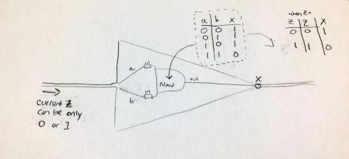
This is a simulation of a simple type of Nand gate, specifically a 3-input DTL Nand gate, on which you can change the inputs and see how it finctions.

It consists of 4 diodes, 2 resisters and a transistor. The three diodes on the left form the 3-input And part of the circuit and the diode and transistor on the right form the inverter. Eliminating one of the left-hand diodes turns this into a 2-input Nand. Eliminating 2 of the left-hand diodes turns it into a 1-input Nand--which has a more common name 8^).

Playing with this simulation should give you an idea for another solution for Not from Nand that doesn't involve tying the inputs together.

--Mark