Registry implemtation alternative without time input

classic Classic list List threaded Threaded
3 messages Options
Reply | Threaded
Open this post in threaded view
|

Registry implemtation alternative without time input

rickx34
Hi,
I have just read chapter 3 and was wondering if 1-bit register could be implemented with just mux. As we have seen in chapter 3 the first cycle of the clock in a 1 bit register the output is unknown which then ofcourse gets a value of 0 or 1 depending on "in" in the next cycle.

My question is can't we just implement 1-bit register with just mux(combination logic) and leave out DFF. A 1-bit register has a mux and a DFF, DFF output is fed back into one of the input pins in mux and that how the "in" value is remembered indefinitely until there is no power. If we exclude DFF and feed the mux output into itself, won't it work the same way. I got images that should explain what im thinking.

image https://www.dropbox.com/s/bnhgxctsp7sc34f/dff.png?dl=0
Reply | Threaded
Open this post in threaded view
|

Re: Registry implemtation alternative without time input

cadet1620
Administrator
The circuit you are describing is called a "D Latch".
  D Latch implemented with multiplexor
When CLK is high, the D input appears on the output. If D changes, the output changes.
When CLK goes low, the current output value is stored and changes to D do not affect the output.

You can see the classic implementation of D Latch using Nand gates here:
    http://www.play-hookey.com/digital/sequential/d_nand_latch.html
I highly recommend the play-hookey site.

You might also want to get Logisim. It's a nice logic simulator that will let you play arround with circuits like this. (The circuit above is from Logisim.)

Consider this: how can you use your mux-based D Latch to make a DFF using only 2 muxes?

--Mark
Reply | Threaded
Open this post in threaded view
|

Re: Registry implemtation alternative without time input

cadet1620
Administrator
In reply to this post by rickx34
Why aren't latches used for registers?

Consider this circuit, which is a part of the CPU that you will build in project 5.
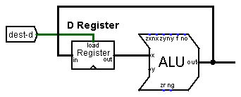
  CPU circuit detail showing feedback loop
When an instruction like D=D+1 executes, the output of the D Register needs to be incremented and stored back into the D Register.

If the D Register is latch-based instead of DFF-based, as soon as the dest-d control signal goes high, the ALU will increment the D Register output and send it back to the D register which will send its new input to the ALU which will....

The circuit will continuously increment as fast as it can.

--Mark