Many people have trouble understanding how the Chip implementation works. I find it helps to draw the logic diagram(s) out on paper first.
But it also helps to understand that the Chip definition represents an outer empty shell, with labeled, or named connections (
think of these as "wires").
The the Parts section are then what goes inside the box. Each part has its own named connections, and those should be
wired together with the equals (
=) statements. And sometimes its necessary to invent a
wire name in order to complete the connection (
and the connection names must be unique).
For example, the XOR gate implementation and a similar drawing is already provided in the required project 1 reading. Here's my own drawing to help visualize the "
outer chip shell" and its "
internal parts connections"
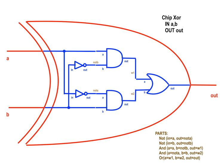
Here we can see how each of the named wires should connect to each other.
The XOR chip definition has named wires, "a", "b", and "out"
One of the parts is an AND gate. It also has named wires of "a", "b" and "out".
So we can see, "a" (
of the AND gate) connects to "a" (
of the XOR shell), and "b" (
of the AND gate) connects to a wire we've named "notb" (
which is also connected to the NOT gate's "out" wire).
Remember, that each internal part must first be previously defined before it can be used in a later abstraction. If you didn't create a NOT or AND or OR gate yet, then you can't use them as Parts definitions yet. Also, you can't use same part that you are trying to create (
an XOR chip can't have an XOR part, because it hasn't been created yet).
Hope this helps.

