With fairly simple modifications, the Hack Computer can be used to demonstrate how the Von Neumann single memory (Princeton) architecture works.
In this architecture there is only one memory address and memory data bus. This means that instructions that access data in memory can not be read and executed at the same time. The simplest implementation to solve this is a fetch-execute design. Every instruction requires two clock cycles to execute, the fetch phase and the execution phase. During the fetch phase, the instruction is read from memory and stored in the Instruction Register. During the execute phase, the instruction executes, reading and writing memory as required.
Hack Computer modifications
First, the ROM32K needs to be moved into Memory.hdl. It will be placed so that it maps into the high half of the address space. This implies that Memory's
address bus expands to 16 bits.
    0   RAM
16384   Screen
23478   Keyboard
32768   ROM
With the ROM moved into Memory, Computer consists of just CPU and Memory.
CPUfe (reset=reset, addressM=addressM, inM=inM, outM=outM, writeM=writeM);
MemoryROM (address=addressM, in=outM, out=inM, load=writeM);
CPUfe is the fetch-execute version of the Hack CPU. When it is fetching instructions the most significant bit of addressM will be 1 so that the ROM is accessed. If a program needs to read data from the ROM, it needs to add 32768 to assembler generated ROM address so that the addressM MSB will be set. (It would be nice to extend the Hack language to make this easier.)
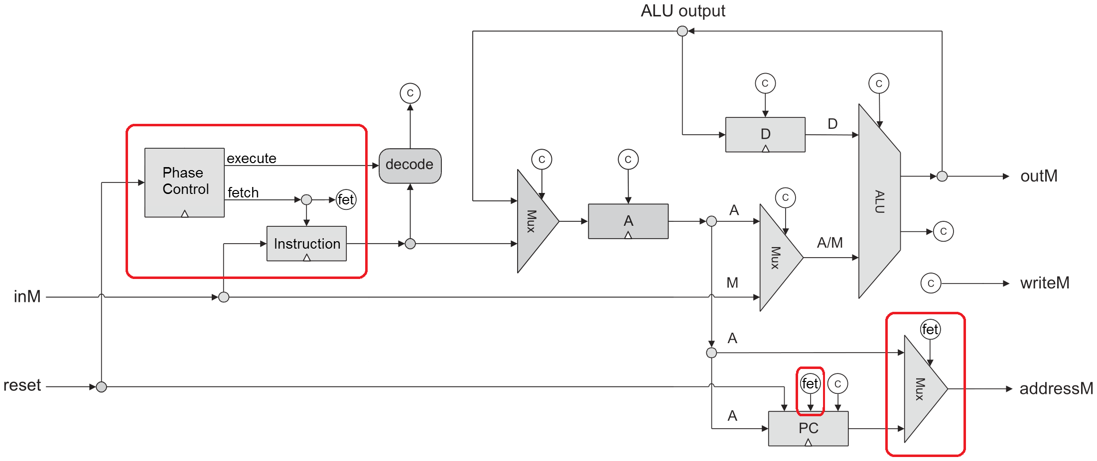
Hack CPU modifications
Phase controller
A DFF with inverted feedback will alternate between 0 and 1 every clock. There is one tricky bit; when the CPU is reset, the phase controller needs to restart with a fetch phase.
// Phase control: alternates between fetch and execute.
// Force to 0 during reset so it restarts in fetch phase.
And (a=fetch, b=notReset, out=phaseIn);
DFF (in=phaseIn, out=execute);
Not (in=execute, out=fetch);
Fetch phase
During the fetch phase, the PC must be routed to addressM and bit 15 must be set.
ARegister (in=aIn, load=loadA, out=aReg, out[0..14]=addressM);
ARegister (in=aIn, load=loadA, out=aReg);
Mux16 (sel=fetch, a=aReg, b[15]=true, b[0..14]=pc, out[0..15]=addressM);
The instruction must be read from memory and stored for the execution phase.
// Instruction register
Register (load=fetch, in=inM, out=instruction,
          out[15]=instruction15, out[14]=instruction14, out[13]=instruction13);
The PC must also be incremented. This must be done either during the fetch phase or the execute phase, but not both. Incrementing the PC during the fetch phase offers the possibility of pipelining the next instruction fetch if the current instruction does not access memory.
PC (in=aReg, reset=reset, inc=true, load=jmp, out[0..14]=pc);
PC (in=aReg, reset=reset, inc=fetch, load=jmp, out[0..14]=pc);
Execute phase
During the execute phase, the instruction that was stored during the fetch phase is executed identically to the original CPU. In my CPU, the only change required was to ensure that the master control signals for A-instructions and C-instructions would only be true during the execute phase.
And (a=notReset, b=aInstBit, out=aInst);
And (a=notReset, b=cInstBit, out=cInst);
DMux4Way (in=execute, sel[0]=notReset, sel[1]=aInstBit, d=aInst); // And3Way
DMux4Way (in=execute, sel[0]=notReset, sel[1]=cInstBit, d=cInst); // And3Way
Does it work?
Here is the modified CPU running the CPUfe.tst:
|time|reset|fet|aIn|cIn| pc  |addressM| inM  |  instruction   |DRegis|ARegis| outM |writeM|
|0   |  0  | 1 | 0 | 0 |    0| -32768 | 12345|0000000000000000|     0|     0|     0|   0  |
|1   |  0  | 0 | 1 | 0 |    1|      0 |     0|0011000000111001|     0|     0|     0|   0  |
|2   |  0  | 1 | 0 | 0 |    1| -32767 | -5104|0011000000111001|     0| 12345|     0|   0  |
|3   |  0  | 0 | 0 | 1 |    2|  12345 |     0|1110110000010000|     0| 12345| 12345|   0  |
|4   |  0  | 1 | 0 | 0 |    2| -32766 | 23456|1110110000010000| 12345| 12345| 12345|   0  |
...
|22  |  0  | 1 | 0 | 0 |   11| -32757 | -7420|0000000000001110|    -1|    14|    14|   0  |
|23  |  0  | 0 | 0 | 1 |   12|     14 | 11111|1110001100000100|    -1|    14|    -1|   0  |
|24  |  0  | 1 | 0 | 0 |   14| -32754 |   999|1110001100000100|    -1|    14|    14|   0  |
|25  |  0  | 0 | 1 | 0 |   15|     14 | 11111|0000001111100111|    -1|    14|    14|   0  |
|26  |  0  | 1 | 0 | 0 |   15| -32753 |  -544|0000001111100111|    -1|   999|   999|   0  |
|27  |  0  | 0 | 0 | 1 |   16|    999 | 11111|1111110111100000|    -1|   999|  -543|   0  |
|28  |  0  | 1 | 0 | 0 |   16| -32752 | -7384|1111110111100000|    -1| 11112| 11112|   0  |
t0: instruction fetched from -32768 = 0x8000 = ROM address 0, and PC increments.
t1: @12345 executes, A register set.
t2: instruction fetched from -32767 = 0x8001 = ROM address 1, and PC increments.
t3: D=A executes, D register set.
t22: instruction fetched from -32757 = 0x800B = ROM address 11, and PC increments to 12.
t23: D;JLT executes and JUMPS, PC = A register set = 14.
t26: instruction fetched from -32753 = 0x800F = ROM address 15, and PC increments.
t27: A=M+1 executes. Memory[A=999] = 11111, 11111 + 1 -> A.
The modified CPU also correctly runs the tests:
[D:/TECS/projects/05/fetch-exe]
% for x in C*.tst ; do echo -n "$x:  " ; HardwareSimulator $x ; done
CPUfe.tst:  End of script - Comparison ended successfully
ComputerAdd.tst:  End of script - Comparison ended successfully
ComputerMax.tst:  End of script - Comparison ended successfully
ComputerRect.tst:  End of script - Comparison ended successfully
[D:/TECS/projects/05/fetch-exe]
Email me if you want the test files.
--Mark
There is a subtle incompatibility with the original Hack computer. Because all 16 bits of the A Register are used to access memory, any code that does something that uses the top bit of pointers to store some information, like an end-of-list indicator, will access ROM instead of RAM.