|
|
|
|
I first read the chapter, and then was struggling to understand the problems, so I went back and read again, and I realized I don't quite understand Figure 1.6.
I read Appendix A, and I am still struggling.
It seems like a very complicated way to write out the Xor function, but I am sure there is a reason for its complication, and I just don't get it.
I don't understand how why the parts are done the way they are.
I tried a canonical representation of Xor that did not do it and I am lost.
If anyone could help, I would be really appreciative, I am STUCK!
Thanks!
|
|
Administrator
|
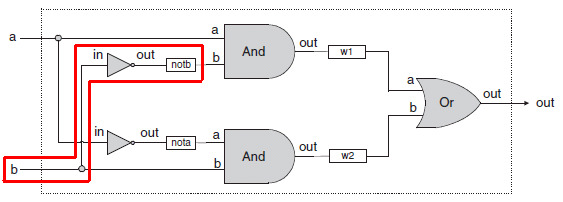
The schematic drawing at the top of Figure 1.6 is the canonical representation of Xor.
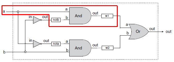
HDL is a description of this schematic. Each logical function in the schematic gets a line in the PARTS: section of the HDL, describing how wires are connected to it.
Make sure that you have downloaded the HDL stub files and test scripts. All you need to add to the Xor.hdl stub file are the Nots, Ands and Or.
WARNING, If you have not implemented Not.hdl, And.hdl and Or.hdl this chip will not work because those stub files have empty implementations. Make a subdirectory and move the Xor.* files into it if you want to work with Xor before you make the chips it uses.
--Mark
|
|
|
Thanks for the reply!
OK, so here is where I am confused:
Based on the chapter, I got the following canonical representation of the function:
f(a,b) = Not(a)b + aNot(b)
Assuming that is right, I am not quite sure how that goes to the Figure 1.6 graph. It seems like it must be using some mathematical equivalence expansion to use the And and Or's, but I am not getting why or how.
Also, the w's are really throwing me off.
I apologize if I am being dense.
|
|
|
Hey Erik,
Did you implement Not, Or and And? As Mark states, you should implement the chips in the project according to the order they are listed in the project page.
The w1 and w2 you see in figure 1.6 are user-defined pins. The names are arbitrary. For example:
MyChip(in=x, out=mySpecialPin);
MyOtherChip(in=mySpecialPin, out=out);
You need to imagine that "wire x" is connected to the input of MyChip, and the output of MyChip is connected to a wire called mySpecialPin. Next, the wire mySpecialPin is connected to the input of MyOtherChip.
Now, in regards to your Xor problem -- take a look at the diagrams. The implementation is right there.
Keep working at this -- once you get used to the HDL things will come together.
|
|
Administrator
|
I'm guessing that the multiple notations are throwing you off. In normal arithmetic expressions we use '×', '·' and juxtaposition to mean multiplication, there are multiple notations for Boolean expressions.
Not can be '~', '!', '¬' or over-line.<br>
Or can be '+', '|', or upside down '^'.<br>
And can be '·', '^' or juxtaposition.
And has precedence over Or. Not's precedence is often ambiguous; use ().
So all of these are the same:
_
ab+cd = (~a)&b|c&d = ((NOT a) AND b) OR (c AND d)
The overloading of '+' and juxtaposition for Boolean operations can be confusing since they look like normal arithmetic.
--Mark
|
|
|
gotcha, so w is a variable.
No, I have not done those examples, and from the book, I have not gotten that I should have, nor do I exactly know how.
I am in section 1.1.4 and that is HDL, and the first example of HDL is the Xor example, and I am just trying to understand it, and I am having a very hard time.
|
|
|
I think I am OK with the notation, the problem I believe I am having is the logic.
I don't see how the canonical function Not(a)b + aNot(b) (assuming that is right)
turns into 5 parts.
|
|
|
It's not a "variable" it's a pin name. There's a difference, since HDL is not a "programming language" per se.
|
|
|
ErikY wrote
I don't see how the canonical function Not(a)b + aNot(b) (assuming that is right) turns into 5 parts.
((NOT a AND b) OR (a AND (NOT b))
How many logical operators do you see?
|
|
|
Understand, I guess what I meant was that I can call it what I want, and the naming convention was variable, but I understand the difference, Thanks!
|
|
|
THANK YOU!!!
This is exactly what I was missing! This makes it very clear!
I still am not quite clear on the translation of each individual part however:
Nota
Notb
Andb
Anda
Or
I am now missing the connection from the canonical function, or whatever it is, to get to the parts code.
Thanks so much!
|
|
Administrator
|
 NOT(in=b, out=notb);
 AND(a=a, b=notb, out=w1);
Hope this makes it obvious.
--Mark
|
|
|
I am sorry for any confusion, that part I did actually understand.
I can translate from the graphical representation.
What I cant seem to get is how the Nota part of the canonical function becomes:
Not(in=a, out=Nota)
Maybe I am just dense and not cut out for this, I hope not, because I really am interested in it and want to learn it.
|
|
|
It's just the name of the wire. Look at Mark's diagram. What is the input to the lower AND gate? It is a wire called "NotA." Where did that wire come from? It is the output of the Not gate.
That wire could be called "elephants," "chicken" or "pumpkin."
Given the syntax of the Hack HDL, how else would you be able to specify that "the wire coming out of the not gate is an input to an and gate" ?
|
|
|
I understand the wiring concept.
the part I cant get for the life of me, and I have been looking at this for 2 days, is how to translate
(Nota and b) or (Notb and a)
to
Not(In=a, out=nota);
Not(In=b,out=notb);
And(a=a, b=notb, out=w1);
And(a=nota, b=b, out=w2);
Or(a=w1, b=w2, out=out);
Does that have to be done by creating the gate diagram, and then creating the HDL off of the gate diagram?
OR, is there an algebraic, or logical pathway I can take to get to the HDL above without the gate diagram?
I am struggling with how to create that gate diagram from the canonical representation.
sorry for being dense.
|
|
Administrator
|
Erik,
Become a registered forum member and you can send me email and we can work this through off forum. Tell me a bit about you background.
--Mark
|
|
|
Erik,
I would recommend reading through the rest of chapter one. I suspect it will all become more clear as you see how to implement not and then and. Xor is not meant to be the first gate you implement in HDL. That wasn't clear to me the first time I read it and I also ran into some snags there.
Sean
|
|
|
Sean, thanks! Mark recommended the same thing, I am going to do just that, and then come back to it.
Thanks to everyone, sorry for being so dense!
|
|