multiplexor / demultiplexor and communications networks (general question)

classic Classic list List threaded Threaded
4 messages Options
Reply | Threaded
Open this post in threaded view
|

multiplexor / demultiplexor and communications networks (general question)

lodowcowy_rowerzysta
Hi!
First of all sorry for my English.
On the lecture was said that the multiplexor and demultiplexor performs opposite functions and this property can be used in communications networks.
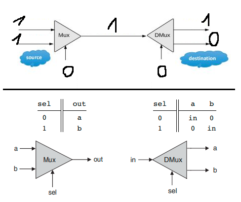
I'm not sure if I fully understand this. I think when we put two ones as input to the multiplexor and then try to invert this process using demultiplexor there will be a problem because one of the ones will turn into zero. I will show what I mean in the example (I set selection pins arbitrarily to zeros):

I don't understand something important? Or maybe that thing that was said on lecture about performing opposite functions and how communication network works was just some sort of simplification?
Reply | Threaded
Open this post in threaded view
|

Re: multiplexor / demultiplexor and communications networks (general question)

WBahn
Administrator
When you use these for communications, you need a synchronized clock at each end so that you apply first a 0 to both Select inputs to transfer the data on one input to the corresponding output and then a 1 to transfer the data on the other side.

So if your data rate on each line is, say, 100 bits per second, the data rate on the single line connecting them would be 200 bits per second with half of it being from one line and half from the other.

If you have a 16 input mux and demux, the data rate on the connecting line would be 16 times the data rate on the individual lines.
Reply | Threaded
Open this post in threaded view
|

Re: multiplexor / demultiplexor and communications networks (general question)

lodowcowy_rowerzysta
I still don't understand. I'm not sure if you answer my question. I wonder how this communcation model handles case when you want to transfer input: a=1, b=1. I think it shouldn't work because one of the input's "1" will be lost due to dmux characteristics (one of the dmux output always is 0 - look at the dmux simplified truth table on picture that I posted). So how is it working despite of that?
Reply | Threaded
Open this post in threaded view
|

Re: multiplexor / demultiplexor and communications networks (general question)

WBahn
Administrator
Whatever is looking at the outputs of the dmux knows when its data is present and when it is not.

This is often done using a DFF (which you will get to in the Chapter 3).

So let's say that you have two data lines coming in with data changing every two seconds.

Your select line changes state every second, so that data on the transmission link on even-numbered seconds is data from the first line while odd-numbered seconds it is from the second line.

At the output of the dmux, the data on the first output is valid data from the first line during even-numbered seconds but it is garbage during odd-numbered seconds. The situation is flipped for the second output.

Following the dmux, you have a register that looks at the data during each even-numbered second and loads that value into the register and holds it for two seconds so that it remains stable and ignored the garbage during the odd-numbered seconds. The other line has a similar set-up.