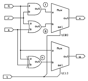
For more complex circuits, I find it helps to draw out the circuit and label all the chip I/O's (IN and OUT statements), and the I/O's in every part used in the circuit. Also assign names to the internal wires that connect the parts.
Example:
    CHIP Foo {
        IN q, r, s, t[2];
        OUT x, y;
    PARTS:
        ...
    }
I don't know what the Foo part is good for, but here's its circuit diagram:

The left side of the '=' is fixed for all parts; it must match that part's IN and OUT declaration. That means that the Foo chip's parts section will look like:
    PARTS:
        And (a=___, b=___, out=___);
        Or (a=___, b=___, out=___);
        Xor (a=___, b=___, out=___);
        Mux (a=___, b=___, sel=___, out=___);
        Mux (a=___, b=___, sel=___, out=___);
(The order of the Part lines, and the order of the connections in each part line, does not matter since HDL is just a description of the schematic diagram.)
Now all you need to do is fill in the blanks.
    CHIP Foo {
        IN q, r, s, t[2];
        OUT x, y;
    PARTS:
        And (a=q, b=r, out=f);
        Or (a=r, b=s, out=g);
        Xor (a=q, b=s, out=h);
        Mux (a=f, b=g, sel=t[0], out=x);
        Mux (a=q, b=h, sel=t[1], out=y);
    }
It often helps to mark the wires on your drawing as you make the connections since the Chip I/O's normally use similar names to the Part I/O pins.
(To help avoid confusion, I intentionally used non-conflicting pin names in the above example. If Chip Foo's I/O's were the normal a, b, c, sel and out, it would have looked like this:)
    CHIP Foo {
        IN a, b, c, sel[2];
        OUT out, other;
    PARTS:
        And (a=a, b=b, out=f);
        Or (a=b, b=c, out=g);
        Xor (a=a, b=c, out=h);
        Mux (a=f, b=g, sel=sel[0], out=out);
        Mux (a=a, b=h, sel=sel[1], out=other);
    }
If you want specific help with Mux4Way16, or more help with HDL in general, email me directly.
--Mark
