|
|
12
|
|
I am having a very difficult time with project 3, I have (after much trial and error) gotten my PC to load into the simulator, but I cannot get in to increment correctly. I am using 3 Mux16's, an Inc16, a Register, and finally- a Mux4Way16. I feel like I am just missing the big picture.
Help!
|
|
Administrator
|
Hunt0037 wrote
I am having a very difficult time with project 3, I have (after much trial and error) gotten my PC to load into the simulator, but I cannot get in to increment correctly. I am using 3 Mux16's, an Inc16, a Register, and finally- a Mux4Way16. I feel like I am just missing the big picture.
You are on the right track with the 3 Mux16s and Inc16. Since you don't mention a bunch of Ors, I'm guessing that you noticed that you don't need to control the Register's load input, just set it to true so that the Register always loads.
The trick is to realize that the if/elseif/elseif/else programming construct in the comments means that reset is the highest priority and inc is the lowest priority control input in the way that conflicting inputs are handled.
reset therefore must choose between 0 and something else as the input to the Register; the output from the Mux16 controlled by reset must be the Register's in. The "something else" needs to be controlled by the next highest priority control input, load.
When you get this written as HDL, it's going to look backwards if you are used to sequential programming.
Email me if you want more direct help.
--Mark

|
|
|
This post was updated on .
Mark,
I believe I understand the chip, and I made some of the changes you
suggested, but I am still coming up with the same error. I have inserted my
code. I think the problem is with the ordering of my first mux/inc.
On Monday, March 25, 2013, cadet1620 [via Nand2Tetris Questions and Answers
Forum] wrote:
> Hunt0037 wrote
> I am having a very difficult time with project 3, I have (after much trial
> and error) gotten my PC to load into the simulator, but I cannot get in to
> increment correctly. I am using 3 Mux16's, an Inc16, a Register, and
> finally- a Mux4Way16. I feel like I am just missing the big picture.
>
> You are on the right track with the 3 Mux16s and Inc16. Since you don't
> mention a bunch of Ors, I'm guessing that you noticed that you don't need
> to control the Register's *load* input, just set it to *true* so that the
> Register always loads.
>
> The trick is to realize that the if/elseif/elseif/else programming
> construct in the comments means that *reset* is the highest priority and *
> inc* is the lowest priority control input in the way that conflicting
> inputs are handled.
>
> *reset* therefore must choose between 0 and something else as the input
> to the Register; the output from the Mux16 controlled by *reset* must be
> the Register's *in*. The "something else" needs to be controlled by the
> next highest priority control input, *load*.
>
> When you get this written as HDL, it's going to look backwards if you are
> used to sequential programming.
>
> Email me if you want more direct help.
>
> --Mark
>
>
>
> ------------------------------
> If you reply to this email, your message will be added to the discussion
> below:
>
> http://nand2tetris-questions-and-answers-forum.32033.n3.nabble.com/PC-Hdl-tp4026543p4026544.html> To unsubscribe from PC.Hdl, click here< http://nand2tetris-questions-and-answers-forum.32033.n3.nabble.com/template/NamlServlet.jtp?macro=unsubscribe_by_code&node=4026543&code=aHVudGxleWNvdXJ0bmV5QGdtYWlsLmNvbXw0MDI2NTQzfDQ4MTQ3MDg1NQ==> > .
> NAML< http://nand2tetris-questions-and-answers-forum.32033.n3.nabble.com/template/NamlServlet.jtp?macro=macro_viewer&id=instant_html%21nabble%3Aemail.naml&base=nabble.naml.namespaces.BasicNamespace-nabble.view.web.template.NabbleNamespace-nabble.view.web.template.NodeNamespace&breadcrumbs=notify_subscribers%21nabble%3Aemail.naml-instant_emails%21nabble%3Aemail.naml-send_instant_email%21nabble%3Aemail.naml> >
|
|
Administrator
|
Hunt0037 wrote
Mark,
I believe I understand the chip, and I made some of the changes you
suggested, but I am still coming up with the same error. I have inserted my
code. I think the problem is with the ordering of my first mux/inc.
You are right, it's the first Mux. It needs to choose between the Regster output and the incremented Register output.
Once you get your PC working, please edit your post to remove the [almost] working code. We don't want solutions in the forum.
--Mark
|
|
|
This post was updated on .
after i came out this design, i checked the answer available on internet.
i realized all answers use **********(deleted as request)***********.
however, my answer is sth like this, is this less efficient or a bad design?
thanks for comments.  code deleted code deleted
|
|
Administrator
|
Using 3 Mux16s reflects the "if / else if / else if" operation described in the comments.
It is a very good insight to see that there are three control signals and that this is good application for a Mux8Way16.
The hardware tradeoff between using 3 Mux16 in series versus 1 Mux8Way16 is a typical space vs. speed choice. The maximum frequency for the counter will depend on how fast the feedback circuit is.
The serial Mux16s will take about 3 times as long as the Mux8Way16, but the Mux8Way16 will be about 2 times the size, depending on the IC technology used.
You don't need the any signal in your PC. Since the Mux selects the DFF output in the inc=load=reset=0 case, the Register can have it's load permanently true.
--Mark
[Please edit your post to remove the working HDL code. We want students to develop their own solutions.]
|
|
|
thanks Mark
thanks for always pointing out the key idea.
appreciated 
|
|
|
I encountered the same problem.
I thought I had understood the function of 'PC'.
If only used combinations logic circuit, it will direct output the value,that is out(t) = out(t).
so it's must be use a 'Register' to implement the behavior out(t) = out(t-1).
I also understood the priority of 'if else', that is reset > load > inc.
Following is some function diagram of testing process:
Fitst,I thought 'Register' should be at the last postion,but 'PC.hdl' didn't work well.
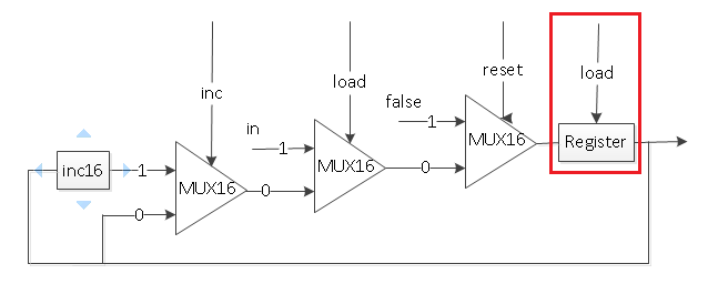 Second,I moved 'Register' to the second last postion,it didn't work.
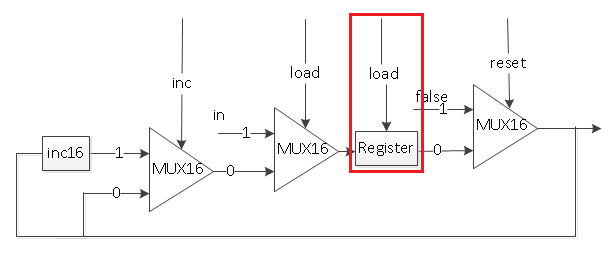 Third,I moved 'Register' to the postion before 'Mux16 with load input', it didn't work.
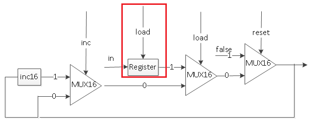 And what really baffles me was: Which postion should I put the 'Register' ?
--Desmond.Song
|
|
Administrator
|
Your first diagram is correct. The output of the Register is the output of the PC.
If you have correctly written the HDL to reflect that diagram and it does not pass PC.tst, then something else is wrong.
You should be working in the nand2tetris/projects/03/a directory.
You must have working and tested Bit and Register in that directory.
You should not have copied any other .hdl files into that directory.
When PC.tst fails, you can single step it to run more of the test cases. Comparing the expected (compare) values with the actual output values should give you clues about what's wrong.
You appear to be a "tactile" learner like I am; you need to draw things out to help understand them.
I recommend that you get Logisim. It's a schematic based logic simulator that you can use to draw and explore your designs. If you would like, I can mail you your PC design as a Logisim file to help you get started with Logisim.
--Mark
|
|
|
Desmond, be sure to check what is wired to the a and b inputs of each Mux16. Looking at your first diagram, when inc is on, what signal should be propagated through?
|
|
|
Thanks, Mark! I had download the ‘logisim’ form the website.
|
|
|
This post was updated on .
Hi Ybacos, thanks.
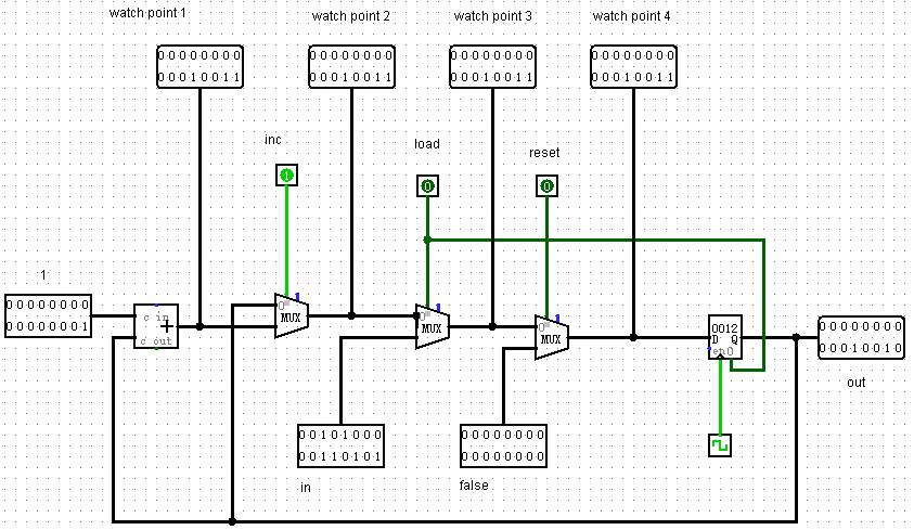
According to your suggestions. I had text and following is results:
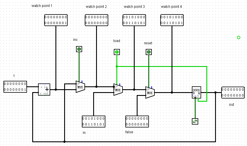
when 'inc' is on, 'watch point 1 to 4' and 'out', every signal is updating value and they are synchronous except 'out' signal because 'Register' is used falling edge to trigger update 'out'.
I think this is right. Do you agree with me? Flowing is my test screenshot.
 --Desmond.Song
|
|
|
This post was updated on .
Mark,I had used the 'logisim' to test my first diagram, the problem was still being, see it below:
 It looks like this, when 'reset = 0' and 'inc = 0', I set 'load = 1', then 'watch point 1-4' is continuous updates but 'out' hold the previous value.
Following are my 'PC.hdl', it also didn't work well.
CHIP PC {
IN in[16],load,inc,reset;
OUT out[16];
PARTS:
// Put your code here:
Inc16(in=outFeed,out=incMux);
Mux16(a=outFeed,b=incMux,sel=inc,out=loadMux);
Mux16(a=loadMux,b=in,sel=load,out=resetMux);
Mux16(a=resetMux,b=false,sel=reset,out=loadRegister);
Register(in=loadRegister,load=load,out=outFeed,out=out);
}
Thank you again for your help !
--Desmond.Song
|
|
Administrator
|
In your HDL, the problem is with the 'load' input for the Register.
The Register must be updated when any of the control signals, 'inc', 'load', or 'reset' is true.
Since the Mux16s select 'out' when all the control signals are false, the Register can be updated in that case too.
Therefore, the Register can be loaded every clock tick, ignoring the values of the control inputs, by setting load=true.
This has the effect of turning the Register into a DFF16. The PC then works like the Bit, with the 3 Mux16s and 3 control inputs replacing the single Mux and control input in the Bit.
-----
In your Logisim circuit, you have the 'load' input connected to the Register pin labelled '0'. This is the 'reset' input the the Logisim register. The load input is the pin labelled 'en' (for 'enable') on the left side below 'D'.
I sent you an email titled 'PC using Logisim'. If you have not seen it, check your spam.
--Mark
|
|
|
Thanks, Mark.
Thanks everyone.  It took me nearly one week to figure it out, but it was worthwhile for me.
|
|
|
This post was updated on .
CONTENTS DELETED
The author has deleted this message.
|
|
|
brrrknee, I wouldn't say it's misleading. Rather, it describes the conceptual behavior pretty accurately. Your goal is to translate that concept into hardware.
|
|
|
Thank you so much!
I had been struggling for days over this chip before I stumbled across this post. Thank you for all the work you guys do!
|
|
|
What a fascinating thread! I struggled with the PC chip some yesterday. Many thanks to Mark for turning me on to LogiSim... instead of spending the day today trying to draft PCs on paper I learned enough about LogiSim to start building a set of chips based on 2-input NAND gate logic: Mux, DMux, FullAdder, HalfAdder, Add16, Or3Way, Mux16, Inc16, Bit, Register16b, Or4Way & Not16... And used those to build my PC.
Possible Spoilers Ahead:My final chip spec requires:
1 Register
1 Inc16
2 Mux16
6 NAND
So, when I was looking through comments here and saw some people are pinning the Load pin of their Register, I thought, oh cool, I can nix those 6 NAND gates I threw in (as an Or3Way).... But when I pull them and "pin the load" I'm no longer passing the unit tests... To elucidate further, allow me to post to a pastebin of my chipset ( PC.hdl - working) Please don't follow this link unless you want to see my working specification.I also note that it seems these same designs I'm referring to were using a trio of Mux16, while I've already noted mine works with only 2... so, perhaps that's where I need to explore to understand the differences between my design and whatever it is y'all are doing... Time to go looking at some solutions on GitHub, perhaps.
It's a lot of fun to play researcher and "discover" (granted, I'm following a trail of well-placed bread-crumbs) thanks to Noam, Shimon and their team, as well as communities like this: the fundamentals of what, quite literally, makes computers tick.
|
|
Administrator
|
Tying Register's load input to true effectively turns it into a DFF16. Then you can think of the PC as having the same topology as the Bit, except that the input Mux in the feedback circuit becomes a more complicated circuit.
Although you don't need it for PC, from a high level point of view, since you have an Or8Way, you already have an Or3Way:
Or8Way(in[0]=a, in[1]=b, in[2]=c, in[3..7]=false, out=x)
--Mark
|
12
|

