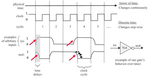
Sorry, but the slide in the OP has issues. Consider just the boxed portion:
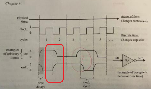
The top is the signal at the input of a Not gate, while the bottom is the output of that same gate.
Notice that the output starts changing immediately at the vertical dashed line (that the line is synched to the clock is immaterial, just use it as a reference point). While the input remains at the same level for a bit and then falls.
Furthermore, the shape of the edges is unreasonable. The rising edge of the output waveform is about what you would expect, namely a rapid initial rise and then tapering off into the final value (these circuits tend to exhibit first-order exponential transitions or close thereto). But the input signal starts off by changing slowing and then accelerates until making an abrupt stop at the final value.
As I noted in a prior post, some of the in/out pairs show reasonable relationships (ignoring the transition shape issue), but others do not. Specifically, the two pairs associated with a falling input require the gate to be psychic.
A note on terminology -- saying that the voltage level is "gated" is not standard terminology (might be a to-English translation issue).
Actual gates have a few defined thresholds.
VinLO -- Voltages below this are guaranteed to be recognized as a logic LO
VinHI -- Voltages above this are guaranteed to be recognized as a logic HI
Voltages in between this are indeterminate. Whether they will be treated as a HI or a LO is not specified or guaranteed. The actual transition point simply somewhere between them and different gates, even on the same integrated circuit, will have different thresholds. Furthermore, the same gate may recognize a particular voltage in this range as a LO today and as a HI tomorrow, just because the chip is at a different temperature.
Similarly, the outputs also have defined ranges.
VoutLO -- The output is guaranteed to be no higher than this when the output is LO and the gate is not being asked to sink more current than it is rated for.
VoutHI -- The output is guaranteed to be no lower than this when the output is HI and the gate is not being asked to source more current than it is rated for.
These limits are designed so that VoutLO is comfortably less than VinLO and, likewise, VoutHI is comfortably higher than VinHI. The differences are the noise margins built into the design.
For CMOS, the actual transition point tends to be pretty close to the midway point because designers like circuits that behave symmetrically. The difference in input voltage between when a specific gate is asserting one level and when it asserts the other level is quite narrow, just a few millivolts or even well under a millivolt in most cases. This is one of the reasons why it is reasonable for timing specifications to be drawn based on the 50% levels of the input and output waveforms, which is the standard practice.